

Venkel Ltd. just released the new CRG – RoHS 6/6 “Green” resistor new product offering this month on September 3rd, 2014. This new resistor series is a general purpose Thick Film Resistor. It incorporates new construction materials whereby Lead in the glass and Lead Oxide in the resistive element is now eliminated. The glass frit contained within the resistive element (RuO2) no longer contains any Lead or Lead oxide and will meet the RoHS 1000ppm or 0.1% threshold without taking the 7C-I exemption.
This product is being produced and released in the industry due to the fact the 7C-I exemption will be expiring on approximately July 1, 2016. (There is a chance the 7C-I exemption could be delayed if enough companies request an extension and an extension is approved by the EU).
A new product data sheet along with material declarations and reliability data are now available on-line at www.venkel.com. SGS or Interek material reporting validation data (verifying all the material compositions or MDS’s) will be forthcoming within the coming months and available by the end of the year. Besides the material differences, there are differences in the resistance ranges and in the Temperature Coefficient of Resistance (TCR) when compared to Venkel’s CR series General Purpose Thick Film Resistors. In some cases, depending on the size and value needed, the TCR may be higher. The wattage ratings are considered industry standard such as the 0402 and 0603 which are rated at 1/16th Watt (0.0625W) and 1/10th Watt (0.10W) respectively.
Although the exemption is not set to expire until July of 2016, numerous customers have requested that we have a complaint alternative available now. Depending on each company’s situation, some must have a strategy in place in order to get new products tested, verified and released. Many companies want to get ahead of the game on this mandate so no bottlenecks or delays will occur prior to or after the deadline.
The new CRG series resistors are available now. This series enables you to have your products fully RoHS 6/6 (if that specific resistor product line was the only commodity preventing you from being fully RoHS 6/6 compliant). Please let us know if you have any questions regarding this new product release and if samples are needed for qualification purposes and we will do our best to accommodate you
Sincerely,
Nathan Bailey
Although the exemption is not set to expire until July of 2016, numerous customers have requested that we have a complaint alternative available now. Depending on each company’s situation, some must have a strategy in place in order to get new products tested, verified and released. Many companies want to get ahead of the game on this mandate so no bottlenecks or delays will occur prior to or after the deadline.
The new CRG series resistors are available now. This series enables you to have your products fully RoHS 6/6 (if that specific resistor product line was the only commodity preventing you from being fully RoHS 6/6 compliant). Please let us know if you have any questions regarding this new product release and if samples are needed for qualification purposes and we will do our best to accommodate you
Nathan Bailey

.png?width=1276&height=1545&name=figure1-post3%20(1).png)
.jpg?width=600&height=587&name=figure1---z-vs-freq-of-mlcc%20(1).jpg)
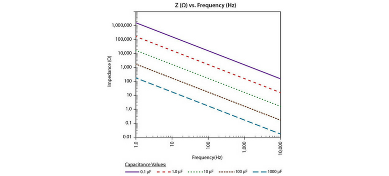
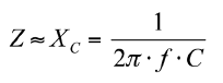 From this relationship, it is clear that the impedance of a capacitor is dependent upon frequency and capacitance value. So why does the electronic industry make a standard to measure a 10uF MLCC at 1KHz but a 15uF at 120Hz?


