Celebrating 30 years.

Resource Center

Articles, datasheets, technical data, cross reference guides and more. All in one place.

Articles

Capacitor ESR: It’s EaSieR than you think!

Posted by Mike Randall on August 20, 2014

1

Equivalent series resistance or ESR is a measure used to characterize the real portion of the impedance of a capacitor.  This is the resistance (R) that the impedance curve typically hits at series resonance, and ESR is commonly used to characterize that value.  For a perfect capacitor ESR is 0.  But, with the possible exception of CronutsTM, nothing is perfect, so we mortals must accept real capacitors. 

At and near resonance frequency, ESR defines the impedance (Z) of a capacitor.  At lower frequencies, impedance is largely controlled by capacitive reactance (XC) and at higher frequencies Z is controlled mainly by inductive reactance XL.  Inductive reactance is controlled by inductance (L), and is commonly characterized by equivalent series inductance or ESL, in a manner analogous to using ESR for R.  A typical model for a real capacitor at frequencies below and near resonance is a capacitor and a resistor in series as illustrated above.

Fun with Math

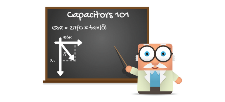
ESR is related to other performance measures of a capacitor as well.  Dissipation factor or df is the measure of the ratio of a capacitor’s real resistance (ESR) to its capacitive reactance (XC).  Df is equivalent to the tangent of the angle between ESR and XC as illustrated above.  This angle is commonly called delta (δ) and so df = tan(δ).  The cartoon above illustrates the geometry between XC, ESR and δ. 

The inverse of df is the quality factor of a capacitor, also known as Q.  So Q is a measure of the “perfectness” of a capacitor as Q=1/tan(δ).  Since tan(δ) = ESR/XC, Q = XC/ESR.  Following this logic, ESR = tan(δ)/XC = 2πfC·tan(δ) = 2πfC·df and the power dissipated by a capacitor at a given frequency near resonance is P = I2·Z ~ I2·ESR.  So, as ESR is increased, the amount of power dissipated in the capacitor for a given current flow (I) increases.

What does all that mean?

So now that we know what ESR is and how it works, when should we select a capacitor with a higher ESR and when should we select a capacitor with a lower ESR?  That seems obvious, right?  We want to be as close to perfect with our capacitor as we can be, right?  Not so fast my friends!  Zero ESR, just like CronutsTM, may not always be your best choice in our real world.   

When to Use Low ESR

There are situations where it is true that, lower ESR in the capacitor selected is better.  For example in band pass or notch filtering, the high Q (and low ESR) of the device selected helps to increase the amount of signal passed over the range of frequency of interest while blocking signal outside of the frequency range of interest.  In this case, the capacitance value is selected, in combination with the knowledge of the device’s inductance, in order to achieve resonance at the frequency of interest (f0), using the relation f0 = 0.1592·(L·C)-1/2 = 1/[2π√(L·C)].  Selection of the appropriate capacitor value will define a frequency “notch” wherein the impedance is suitable to pass current over a range of frequencies that is defined by its associated impedance curve.  The edges of this frequency range are typically defined by a 3 decibel (dB) change in signal intensity from the base Z curve and the effectiveness of the filter is typically defined by the rate of change in passed frequency intensity with changing frequency, in units of decibel per decade of frequency or dB/decade.  High Q and low ESR capacitors are used in these applications because the lower the ESR, the lower the impedance at resonance and the greater the amount of signal passed at f0 and the higher the dB/decade of the filter.   As a definite and consistent frequency (f0) is needed for the circuit to filter properly, highly consistent capacitance values are needed as are consistent ESL and ESR, so that the filter will perform the same in all devices using the design.  Because of this, it is prudent to use tight capacitance tolerance, low ESR NPO/C0G MLCCs for this application such as those available through Venkel.  For this application, G (+/-2%) tolerance class or better C0G/NPO MLCCs are typically used.

In another application (when designing for power distribution over low-to-moderate frequencies), it is important to strive for a relatively flat impedance curve over a broad range of frequencies.  Tantalum capacitors are ideal for this application and use of low ESR Ta capacitors can enable the use of lower part counts in achieving your “low and flat” Z goal.  Such low ESR Ta capacitors are also available through Venkel.  Another potential option for this application is selection of controlled ESR MLCCs, having increased ESR over standard MLCC designs.  Controlled ESR MLCCs also typically have low ESL, making them ideal for applications requiring higher switching frequencies.  Unfortunately, however, controlled ESR MLCCs are not generally available and they are typically very expensive.  Because of these factors, low ESR Ta is still the capacitor of choice for this application.  And if higher switching frequency is needed, standard configuration MLCCs or low ESL MLCCs are used in the power distribution network (PDN) to complement the low ESR Ta capacitors as needed.

When Low ESR can be a Problem

As with CronutsTM, it is possible however to “go too far” with low ESR, and the designer must be careful to avoid these situations.  An example of this is when the ESR of the capacitor selected is very low and the range of application frequencies used in the design includes frequencies that are significantly higher than the series resonance frequency (f0) or SRF of the capacitor selected, such that parallel resonance occurs.  When use frequencies exceed the parallel resonance frequency (PRF) of at least one capacitor in the circuit, a low ESR may not provide enough impedance to the resonating portion of the circuit in order to properly dampen the parallel resonance.  In this case, a “tank oscillator” is established and the impedance curve may have sharp, resonance peaks, in direction opposite to the series resonance peak on the impedance curve, over the high frequency portion of the use frequency range of the impedance curve.  This may result in unwanted behavior of the circuit, such as the introduction of noise to the circuit or the like.  These phenomena are generally undesirable and may be addressed via proper capacitor selection, including proper selection of capacitance value, tolerance, and increased ESR values, such that parallel resonance is avoided, or at least dampened properly.  Parallel resonance can also be avoided or reduced by mounting the high frequency MLCC(s) selected for you design onto your circuit in a manner such that the internal electrodes are oriented vertically.  This, in effect, removes the odd harmonics of the parallel resonance of a capacitor, including the first harmonic, and increases the usable frequency range to below the second harmonic of the PRF. 

In Conclusion:

So, we have discussed ESR and associated loss factors and we know that, generally, low ESR is good.  We also know now that, for band pass and similar filtering situations, it is important to use tight tolerance, high Q, low ESR capacitors (NPO/C0G MLCCs) with consistent capacitance value, consistent ESR and consistent ESL.  We also know that low ESR Ta capacitors are generally the capacitor of choice when designing for flat Z over a broad range of frequencies from low-to-intermediate frequencies for power distribution applications or the like.  Finally we know to be careful to avoid deleterious effects of parallel resonance when selecting capacitors for high frequencies, and that we can do this through prudent capacitance value selection as well as use of moderate ESR MLCCs and/or making sure that the frequency range of our design does not encroach a PRF of any of the capacitors in the circuit.  We also know that PRF can be increased by mounting the MLCC of interest with its internal electrodes oriented vertically so as to eliminate odd harmonics (including the first PRF harmonic). 

Whew!  That was exhausting…I need a CronutTM!  TTFN!

Tags: esr, capacitor, high-q, esl

Testing High Capacitance Multilayer Capacitors, Measurement, Accuracy – Part 3

Posted by Nathan Bailey on August 12, 2014

22 


This is Part 3 of a Four Part Series

Hello fellow engineers and circuit problem solvers. We have a lots going on ‘round here and as we keep adding important and relevant data to our website and catalog. Just like you, there is much more to do but we are well on our way and making improvements in many areas. This month’s blog is #3 in a series of 4 related blogs regarding the testing and best practices for testing high value or high capacitance MLCC’s. This month will blog will expand on the information we have discussed and the 4th in the series will end with a general summary of all the aforementioned best practices for testing these high value MLCC’s.

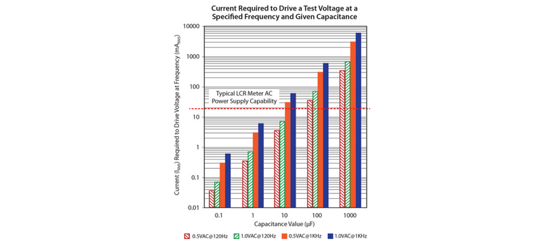
What happens when you attempt to measure a high value MLCC with an LCR tester not suited (i.e.- it does not have and adequate power supply to provide the DUT the with the necessary rms test voltage) for measuring high value MLCC’s with low Z and ESR? Answer: The tester will not supply the necessary AC test voltage and it will drop below a minimum specified level to provide the DUT with enough AC test voltage giving you an artificially low capacitance reading and leading you to believe that the capacitors are out of specification. You may set the test voltage to 1.0 V but many testers will not provide the true “selected” voltage and the actual test voltage applied to the DUT will probably be in the 0.3V-0.7V range due to the low impedance. Following is a graph of a table I supplied in the previous post on this subject showing capacitor impedance at 120Hz and 1kHz and the current required to the test voltage (Arms):


Table 1

figure1-post3 (1)


Figure 1

This graph from the previous data supplied reveals that the test voltage may be reduced from 1.0V AC to 0.5 V AC which will further extend the capability of a capacitance meter with regard to AC test voltage. One of the question I have heard is: Why do most manufacturers specify a test frequency of 120Hz and a test voltage of 0.5V AC above 10uF but specify 1KHz for 10uF and below? The answer is typically known to be from the fact that Tantalum capacitors were specified to be measured at 120Hz and 0.5V so therefore the specification for higher value MLCC’s ( >10uF) were also measured at the same and lower test frequency and Voltage.


The use of 0.5V AC test voltage instead of 1.0V may enable a more accurate measurement of capacitance for values over 10uF such as the 22uF, 33uF(not as commonly made or utilized in our industry), 47uF , 100uF, 150uF, and the 220uF which is highest value MLCC in our industry in a 1210 package. This is especially the case when the LCR meter only has an AC current capability of 20mArms as by the red dotted line in the presented graph. Some LCR testers have enhanced current capability that may deliver up to 200m Arms which will be more effective in obtaining accurate capacitance measurements when values exceed 10uF and above.


In the next bog and final of the series of 4, I will make a recommendation on testing what I consider the unique value on in our industry, the 10uF. So as a precursor, the 10uF has a test specification of 1KHz and 0.5Vrms but a 12uF or 15uF has a test frequency and voltage of 1.0V rms and 1KHz. So in a span of 2uF’s, you change it while the layer count will not increase proportionately to its value or build up of active area within the capacitor. We will discuss and summarize the results in the next blog so until then, happy specification investigating and problem solving!

Until next time…

Nathan

Tags: esr, lcr, capacitor, MLCC

Class 1 Ceramic Capacitors are First Class

Posted by Mike Randall on July 09, 2014

6

Greetings designers!  Until to now, we have discussed Class 2 dielectric (usually ferroelectric) MLCCs.  These are excellent capacitors, having a high very volumetric efficiency or capacitance per unit volume.  But, as we have discussed in previous blog posts, they have some drawbacks, such as temperature and voltage sensitivity of capacitance, etc.  In most cases, circuit designers can circumvent these issues and these devices are ideal for their applications.  But what happens when you need high temperature or voltage stability, or when you cannot tolerate piezoelectric or micro-phonic effects or capacitance aging?  In that case, there is a solution; you need a “first class” dielectric…you need Class 1 dielectric in your MLCC.  Class 1 dielectrics will help you meet your stability needs at the expense of capacitance per unit volume, compared to Class 2 dielectrics. 

Enter Class 1 Dielectric MLCC

Class 1 dielectric MLCCs are comprised of a different type of dielectric chemistry that does not exhibit ferroelectric behavior.  They are generally termed linear dielectrics.  Class 1 is an Electronics Industry Association (EIA) designation and these dielectrics are typically based on magnesium titanate, or calcium titanate, or neodymium titanate, or barium neodymium titanate or strontium calcium zirconium titanate materials, or the like.  They are called “linear dielectrics” because their dipole response associated with changing electrical field is linear in character. These dielectrics are highly stable with respect to numerous environmental factors.  They exhibit properties (primarily K and df) that do not change appreciably with changing temperature or voltage or pressure, or frequency, etc.  Additionally, they do not age (i.e., loose capacitance over time), and they do not “buzz” or convert vibration to output signal noise.  The most common designation within Class 1 dielectrics is the C0G.  There are numerous other designations for Class 1 dielectrics as well, such as C0H, etc.  More specifics about these designations may be found via the following link.  C0G is the most common and the most stable EIA Class 1 dielectric designation.  Many people (usually us “old timers”) still call it NPO, even though the two designations really shouldn’t be used interchangeably.

A Stable Ally

If you need a highly stable capacitor of value ~0.22 µF or less for your 100V or lower rated application, you should consider C0G MLCC (high voltage versions are available as well).  These capacitors are very stable with respect to temperature (i.e., capacitance varies +/- <=30 ppm/C from -55C to +125C), they typically have dissipation factors (df) well less than 0.1% and they do not experience capacitance aging.  They also have very low dielectric absorption and they do not exhibit significant piezoelectric or micro-phonic effects.  Class 1 C0G MLCCs also typically have low ESR and relatively low ESL and are typically available in sizes from 2225 (EIA) down to 01005 (EIA).  You will give up about 100 fold capacitance per unit volume with respect to Class 2 MLCC or tantalum capacitors, but Class 1 MLCC can have volumetric efficiencies that are equal to or better than film capacitors.  C0G MLCCs are also highly reliable and can be quite robust mechanically, if the dielectric used is zirconate based (SCZT or the like). 

Recent Developments

Just as with Class 2 dielectric MLCCs, Class 1 MLCCs have advanced over the years as well.  C0G MLCCs are now available with base metal internal electrodes (BME) and with relatively thin layers (~4µm dielectric thickness or less) and with very high layer counts (over 300 layers in some cases).  This has enabled a strong increase in capacitance per unit volume in C0G MLCCs, similar to the volumetric efficiency advances with Class 2 dielectric MLCCs discussed in previous blog posts.  However, the dielectric constants are still relatively low (ranging from ~10 to ~100 in most cases) as compared to Class 2 dielectrics (which typically exhibit dielectric constants on the order of 3,000 or higher), so even though C0G MLCCs have advanced greatly, it is still about 100 fold less than Class 2 MLCC with regard to capacitance per unit volume. 

Additionally, new SCZT (strontium calcium zirconium titanate) based dielectrics with either precious metal internal electrodes (PME) or base metal internal electrodes (BME) enable relatively high rated voltage per unit dielectric thickness.  This has enabled highly robust C0G MLCCs such as an EIA 1206 (3216 metric) 50V rated 0.1 µF, for example, that is basically “bulletproof.”  These dielectrics are robust with respect to temperature stability, df, and reliability.  Finally, the advent of low K dielectrics combined with copper BME internal electrodes in a Class 1 dielectric MLCCs has enabled very high quality factor (Q) capacitors that are excellent for high frequency applications.  These advancements have enabled the development of C0G MLCCs that are suitable for most needs at or below 0.22 µF.

First Class all the Way!

Class 1 dielectric MLCCs have advanced in a manner that is similar to Class 2 MLCCs.  In the same vein as “A Farad on the Head of a Pin for Free,” you can now get more capacitance in a smaller package, for less $, all with higher voltage rating and better reliability.  So when you need a stable, robust capacitor in the 0.22 µF or less range, always look for the C0G MLCC solution first, because Class 1 dielectrics are definitely First Class.  TTFN!

Tags: tantalum capacitors, esr, tantalums, Capacitors, ferrite beads, esl

Subscribe to Resource Center Updates