
(This post is part of a series. See Part 1 to get caught up.)
Hello fellow engineers, task masters, and problem solvers. Hope all is going well and productive in your world. Well, it looks like Test machines and LCR meters have been at it again – not supplying the correct and adequate test voltage to a high value ceramic capacitor when undergoing testing to determine if their capacitance is within specification for these little multi-layer ceramic devices (components)].
Because the current required to drive a 1KHz signal across a 10μF DUT (device under test) capacitor at either 0.5VAC or 1.0VAC may exceed the AC current capability of a typical LCR meter, it may not be best (in order to obtain an accurate reading) to measure capacitance values of 10μF or above at 1KHz, as this may cause the test voltage at the DUT to be reduced significantly below the set value, leading to erroneously low measured capacitance. This is certainly the case for values from 22uF to 220uF but the 10uF seems to be a special case as all manufacturers call for the 10uF to be tested at 1V RMS and 1KHz. I know you have heard the phrase “ if all else fails – read the directions – we’ll, in this case it would be the owner’s manual of your capacitance meter. Reading it will help you understand the current capability of its power supply. If the current capability of the power supply of your meter exceeds approximately 70 mARMS, it may be suitable to use it to measure capacitance of 10μF capacitors at 1 KHz. Otherwise, it may not be suitable to test at 1KHz, and may be necessary to measure capacitance at 120Hz in order to obtain the actual capacitance value (or at least get close to it). I will go into the 10uF case at another time but for now, here is some data that will help set this all up and hopefully provide some insight into this issue (or maybe it’s better termed as an “on-going challenge”).
The impedance values at two common measurement frequencies (120Hz and 1000Hz) for the same capacitance values is indicated in Table 1 below:
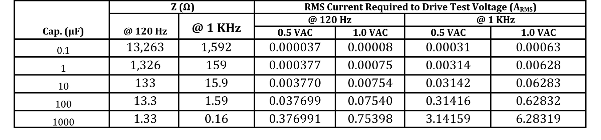
Table 1. Impedance of a MLCC at 120Hz & 1KHz
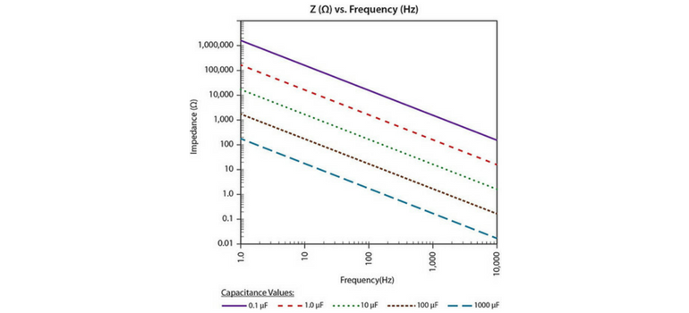
The impedance (Z) vs. frequency relationship of capacitor values ranging from 0.1μF to 1000μF is illustrated in the figure 1 below:
.jpg?width=600&height=587&name=figure1---z-vs-freq-of-mlcc%20(1).jpg)
Figure 1. Z vs. frequency for MLCC’s for a large range of capacitance values
So what does this all mean? How can it help me understand my test set-up and results? What should I do to get better and more accurate results? Questions that we will discuss and go into further detail next time. For now, keep solving those problems and remember, there is no “failure”, only feedback. It may be bad or good feedback, but it’s still feedback.
Until next time.


