Celebrating 30 years.

Resource Center

Articles, datasheets, technical data, cross reference guides and more. All in one place.

Articles

High Voltage MLCCs: Shocking Revelations!

Posted by Mike Randall on September 25, 2014

18

This is Part 1 of a Three Part Series

  • Part 1:It’s What’s Inside that Counts
  • Part 2:Judging a Book by Its Cover:Don’t Forget the Outside
  • Part 3:It Ain’t the Volts, It’s the Amps:Some Applications and Considerations

Greetings fellow components users!  I hope that you have been well.  Have you ever had the need for a high voltage surface mount capacitor, but weren’t sure how to select the right one, or wondered how they are made, or were concerned about the factors you need to be careful of when designing them into your circuit?    In my next three posts, I will try to provide some “enlighteningment” on the subject. 

Surface mount high voltage MLCCs usually appear to be identical to standard MLCCs.   High voltage MLCCs are typically available in EIA size from 0603 to 2225 or larger with voltage ratings from 200V to 5,000V or more.  Smaller case high voltage MLCCs typically have lower maximum rated voltages (VRated) as the external terminals tend to be closer to each other in comparison to larger case high voltage MLCCs. 

High voltage MLCCs are generally available with Class 1 (C0G) or Class 2 (Ferroelectric X7R) ceramic dielectrics with tolerances as good as +/-5% or better, to as wide as +/-20% or higher.  Because of the generally thicker dielectric thicknesses used in the design and potentially the “cascade” or “floating electrode” type designs used, the maximum capacitance values available are significantly lower than analogous low voltage rated MLCCs.   Generally available capacitance values range from ~1 pF to 2.2 µF or higher.   The ESR is also typically a little higher compared to analogous standard MLCCs, but is still quite low (typically ≤10 mΩ).  So what makes high voltage MLCCs different from standard MLCCs?

The More Things Change, The More They Stay The Same

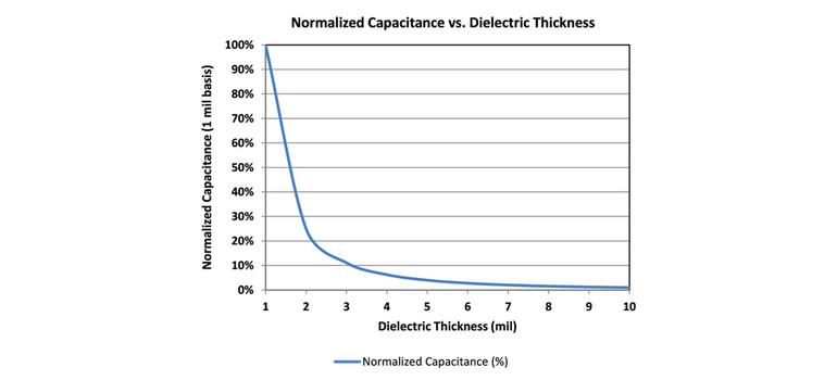
From the outside, high voltage MLCCs look pretty much identical to standard MLCCs, but as my Momma used to tell me, “it’s what’s inside that counts.”  It seems that it should be straight forward to design high voltage MLCCs.  Just increase the dielectric thickness (DT) to enable the desired voltage rating.  The rate of increase in DT is typically about 200 to 250 V/mil (or about 7.8 to 10 V/µm).  We also know that thicker DT results in less capacitance per unit volume (C/V), having a DT-2 relationship as shown in Figure 1 below.  So if we double DT, capacitance is quartered and VRated is doubled.  Simple…right?  Wait just a second!  As it turns out, it’s not quite that simple.

Figure 1.  Approximate normalized capacitance vs. dielectric thickness for standard configuration MLCC

VRated of the ceramic dielectrics used in MLCCs typically demonstrates linear or nearly linear behavior to voltages as high as ~1,000 to ~1,500 V.  But at higher voltages, a different VRated vs. dielectric thickness relationship is observed.  An example of this is given in Figure 2 below.

Figure 2.  Dielectric thickness vs. rated voltage for a typical ceramic dielectric used in MLCCs

For the hypothetical example given in Figure 2, a rated voltage of 1,500 V would require ~10 mil (~250 µm) DT.  This would reduce C/V by a factor of ~100 in comparison to a 250VRated, 1 mil DT MLCC!  If we could in some way maintain the initial linear relationship (~200 to 250 V/mil) we could have used DT of ~6 mil and C/V would have suffered only about a 35 fold reduction in comparison to a 250VRated, 1 mil DT device (i.e., the resulting maximum C/V would be almost 3 times as high in comparison to the case of 10 mil DT).   There must be a way to maintain this relationship, but how?

It’s What’s Inside That Counts

Well, it just so happens that there is a way.  Recalling our freshman EE course, we know that capacitors in parallel are additive, while in series behave in a manner defined by the relation:

We also know that, if all of the capacitors that are in series have the same capacitance value, the above simplifies to:*Cn = Capacitance of capacitor n

formula2
*n is the number of capacitors in series, each having capacitance value Cn
Also, voltage ratings of capacitors in series increase linearly following the relation: 

*n is the number of capacitors in series, each having voltage rating Vn

 Wow!  Using the above relationships, we can increase VRated linearly with a relatively small decrease in capacitance (~C/n).  If only we could fit multiple capacitors in series within a single MLCC…but how?  Well, the structure of a standard configuration MLCC puts multiple capacitors in parallel configuration, so why can’t a clever designer put several capacitors in series configuration, within an MLCC as well?  It just so happens that, long ago, a very clever MLCC designer did exactly that and these floating electrode or cascade electrode design MLCCs have been available for high voltage applications for decades.  Here’s to you, Mr./Mrs./Ms. Clever Designer!

The Details

The basic floating electrode (FE) or cascade electrode designs are illustrated in comparison to a standard electrode configuration design MLCC in Figure 3 below.  From the illustration it is evident that floating electrodes placed between externally connected electrodes result in 2 cascades (or capacitors) per each floating electrode segment used in the design.   One and two FE (or 2 and 4 cascade) designs are illustrated in the figure.  From the figures, we can also see that the electrode active area (A) is reduced with each cascade as well, but if we ignore the dimension of the additional internal margins, the active area is approximately halved for each floating electrode and the rated voltage increases linearly with each internal capacitor in series.

 Because of the reduction in A and the series effect described above, the resulting C/V (ignoring the additional internal margin areas created with each FE) is proportional to 1/n2 (where n is the number of cascades created).  This means that VRated can increase linearly as the number of FEs is increased, with a C/V penalty that is pretty much analogous to the C/V penalty experienced with a standard capacitor configuration MLCC that utilizes increased DT to achieve desired VRated in the linear region below ~1,000 to 1,500 V (i.e., according to the blue line in Figure 2 above).   So now we have a solution to our problem!

Additionally, FE designs largely reduce or eliminate the possibility of short-type failures.  This is because all of the cascades or internal capacitors must fail in order to create a short-type failure.  Thus failure due to flexure cracking or the like is largely mitigated in most cases.  This makes FE type MLCCs also quite valuable in performance critical applications such as across a battery line or the like.

Figure 3.  Illustration of standard vs. floating internal electrode configurations

The Particulars

We can use FE or cascade electrode design to increase VRated with minimized impact on C/V.  As each FE will have an additional margin area associated with it, the impact of additional margins on C/V in small case MLCCs (typically EIA 0603 and possibly 0805) may be prohibitive, but for larger MLCCs (e.g., EIA 1206 to 2225) the impact is relatively small.  As in Figure 4 below, C/V decreases commensurate with (1/2n2), where n is the number of FEs within the design.  VRated also increases with 2n as does ESR.  The effect on ESR is largely compensated however, as the two or more internal capacitors typically have more electrodes in each internal capacitor stack (N), and since the aspect ratio of said electrodes within each of the internal capacitors will have relatively wide and short electrodes, which results in relatively low ESR, so the actual increase in ESR is typically negligible in comparison to standard configuration MLCCs of similar VRated.  Since FE design results in MLCCs having at least two internal capacitors in series, each of the internal capacitors must short in order for the FE MLCC to have an internal short, which is highly unlikely, making FE MLCC highly desirable for applications that are sensitive to short-type failures.  Thus, in comparison to standard configuration MLCCs; with careful design, it is possible to achieve high VRated with minimal increase in ESR and decrease in C/V.  

Figure 4.  Effects of floating internal electrodes on capacitance, ESR and rated voltage

In Summary

Floating electrode (FE) or cascade internal electrode designs may be used to increase VRated of MLCCs with minimal impact on ESR and capacitance per unit volume (C/V) in comparison to standard configuration MLCCs.  Additionally, FE designs largely reduce or eliminate the possibility of short-type failures and thus are valuable in battery line and other critical applications.  For these reasons, floating electrode or cascade electrode designs are typically superior to standard configuration designs for high voltage applications.

Tags: High Voltage, Capacitors, Ceramic, MLCC

Class 1 MLCC vs. Film Capacitors: And The Winner Is…

Posted by Mike Randall on July 15, 2014

7

So, from my last blog post, you are thinking that Class 1 dielectric MLCCs are the “bee’s knees” when it comes to capacitors.  And they are, (I promise…J).  “What about film capacitors?” you ask.  Excellent question!  Let’s explore this topic.

Ceramic versus Film Capacitors

As we have discussed, MLCCs (both Class 1 and Class 2) have advanced greatly with time.  I believe that the rate of advancement of Class 1 MLCC has been faster than that of film capacitors.  I believe that this disparity in advancement has progressed to the point that there is now a pretty clear winner for small case surface mount devices (EIA 1812 and below)…and that winner is…envelope please…COG MLCC.  “Based on what,” you ask?  Let’s explore some more.

What’s Important?

Let’s start with our “Farad on the Head of a Pin for Free” set of goals.  The two types of film capacitor dielectrics that we will use in the comparison are PPS (polyphenylene sulfide) and PEN (polyethylene naphthalate) as these are the most generally available film dielectrics in a surface mount small case configuration. The smallest generally available case size for C0G MLCC is EIA 01005 while the smallest generally available size for film caps is EIA 0603, so C0G MLCCs are available that are ~1/64th the volume of the smallest generally available surface mount film capacitor.  These smaller capacitors take up only ~1/16th of the board space of the larger film capacitors (solder pads not included).  From this standpoint, C0G clearly wins. 

Also, C0G MLCC wins when comparing the highest capacitance generally available at a given rated voltage within a given case size.  For example for EIA 0805 the maximum capacitance generally available in a C0G MLCC is 0.047µF at 25Vrated, and for film capacitors (PPS) it is 0.027µF and 10Vrated.  (Note that you can get metallized acrylic film capacitors in EIA 0805 case size with a maximum capacitance of 0.15µF at 25Vrated, but that type of film dielectric is much more temperature sensitive, and exhibits a much higher dissipation factor and dielectric absorption, as well as a more limited temperature range.  So these types of film dielectrics are more suitable in comparison of tantalum capacitors or Class 2 MLCC and are not a part of this analysis).  The above results are similar for other case sizes EIA 1812 and less as well.

Now for the cost part, comparable PPS film capacitors are typically more than 2X the price of C0G MLCC, and PEN film capacitors are generally more expensive than PPS film caps.  Again C0G MLCC clearly wins. 

Hot Stuff

Let’s compare thermal stability and robustness.  The use temperature range for C0G MLCC is generally -55C to +125C.  PPS has a similar range and PEN is generally -55C to +85C, but some PEN film caps are available having use temperature range as wide as -55C to +125C as well.  Additionally, C0G MLCCs are available for high temperature applications (up to 260C+), so the edge goes to C0G MLCC again. 

Regarding temperature stability of capacitance, C0G MLCC can vary in capacitance no more than +/-30 ppm/C from -55 to +125C as compared to the room temperature (RT) value.  Assuming that RT is 20C, would allow a change in capacitance of as much as ~0.3%.  While PEN cannot meet this criterion, PPS is close so we will call it a tie.  With regard to dissipation factor (df), PEN and PPS both increase with temperature to the point that df at 125C is ~0.4 to 0.5%.  C0G MLCC generally do not exhibit df in excess of 0.1%, but df is not specified at other than RT for G0G, so we will call this a tie as well. 

With regard to thermal robustness, C0G MLCCs generally do not require special reflow profiles for surface mounting as film capacitors do, so C0G MLCC wins here.  With regard to reliability at elevated temperature, C0G MLCCs are generally highly reliable as are film capacitors.  However, C0G MLCCs are generally available with higher voltage ratings at a given capacitance within a given case size.  Also, certain film capacitors can be susceptible to humidity at elevated temperature, so the edge goes to C0G MLCC here as well. 

Other Stuff

So what’s left?  Well, with regard to dielectric absorption or the percentage of capacitance that a capacitor recharges after charging to a certain voltage, and then quickly discharging, C0G MLCC at ~0.5% is slightly better than PEN film at ~0.8%, while PPS film, at ~0.02 to ~0.05%, is the clear winner.  However, unless you are designing a circuit that is highly susceptible to the effects of dielectric absorption, such as a sample and hold analog to digital convertor circuit, this really doesn’t matter much since, even though the PPS value for dielectric absorption is ultra-low, the C0G MLCC value is also quite low (comparing favorably to other films), so the benefit is not obviously applicable in all but a few circuits.  For example in a circuit that charges to 2.5V, then quickly discharges, a C0G MLCC would re-apply a voltage of not more than ~12.5mV to the circuit, while PPS film would not re-apply more than ~1.25mV…both very low values.

With regard to electrical noise generated from mechanical shock, C0G MLCCs have been shown to be superior to film capacitors as well [i].  With regard to resistance to board flexure, film capacitors are generally thought to be more robust, but this can be situation specific as board flexure can pull off external terminations in addition to, or in lieu of, flexure cracks.  This failure mode may be more prominent in film caps as the terminals may not adhere as well, depending upon the termination configuration, materials and application process.  Flex robust C0G MLCCs are also now available, so this is nearly “a wash” with a slight edge going to film caps. 

With regard to self-healing properties, film capacitors clearly win as MLCCs do not self-heal.  However, PPS and PEN have limited to very limited self-healing capabilities compared to other film dielectrics, so this “win” is not very significant.  With regard to solvent resistance, C0G MLCCs are generally superior to film caps as well. 

In Summary

So it is pretty evident that, for small case (EIA 1812 or less) surface mount applications, with few exceptions C0G MLCC are superior to film capacitors.  Additionally, C0G MLCC are considerably more cost effective.  A very good one page summary of the advantages and disadvantages of using NP0/C0G MLCCs versus Film Capacitors .  For the applications discussed above, I think that it is pretty clear that C0G MLCCs are preferable to surface mount film capacitors, so “Winner Winner, Chicken Dinner...COG MLCC.”  TTFN!  

________________________  

[i] X. Xu, et al., “Advances in Class-I C0G MLCC and SMD Film Capacitors,” CARTS USA, Newport Beach, CA, March 2008. 

Tags: tantalum, Ceramic, capacitor, Film Capacitors

Testing, Measurement, Accuracy, Results - High Capacitance Ceramic Capacitors

Posted by Nathan Bailey on June 16, 2014

22

Set-up, measurement, accuracy, test method, result; Words that test engineers know and live by.  We all want accurate results and if you ask 10 test engineers, you might get 10 different answers on how to get there.   When you tell a test engineer that his or her results are incorrect, they may take offense and push back and say they’re ones that are correct and its your products that are out of specification. 

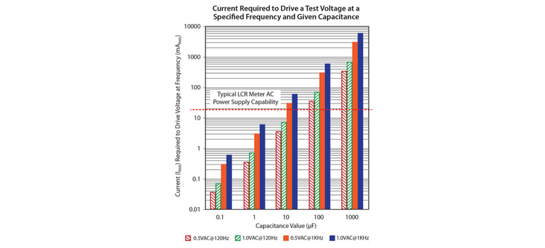
 This is what we find when encountering measurement or correlation issues when endeavoring to measure high value (typically considered to be > 1uF) Multi-Layer Capacitors or MLCC’s.  The inability to accurately measure high value MLCC’s has been an issue in our industry for years with the advent of high value MLCC’s, the issue does not appear to be going away anytime soon. This is due to the fact that many capacitance testers and LCR meters used throughout the industry are not designed to, nor have the capability to correctly measure capacitance of high capacitance (Hi-Cap) MLCCs. This is the case whether we are measuring capacitors at 1 VAC and 1 KHz or 0.5 VAC and 120 Hz. The inability to correctly measure high capacitance MLCCs is due to two reasons. First, many LCR meters do not have the capability of supplying enough current to the capacitor being tested at 1KHz and 1 VAC, resulting in a reduced measurement voltage which results in an artificially reduced capacitance reading. Second, Hi-Cap MLCCs typically utilize Class 2 dielectrics (e.g. X5R, X6S, X7R, X7S, etc.) that are sensitive to test voltage in the sense that changing test voltage results in change in capacitance. Since Class 2 dielectrics are typically made with ferroelectric dielectric materials that are non-linear in behavior with respect to test voltage, this change in capacitance will occur. These two reasons plus the ageing phenomenon (discussed in an upcoming Blog) exacerbates the issue and explains why it is essential to ensure that you apply the correct test voltage to the MLCC when measuring or testing a capacitor and trying to obtain its actual capacitance value. Incorporating the right bridge and applying the correct parameters is essential in obtaining an accurate capacitance measurement.

 To ensure that capacitance is correctly measured, each capacitor must be tested under the correct conditions. The correct conditions for measurement depend upon the capability of the measurement equipment as well as the nominal capacitance to be measured. Since Capacitance measurements are typically performed in the low range of the frequency scale around 120Hz-1KHz, the capacitive reactance (XC) typically dominates the impedance equation, and Z may be estimated from the relationship:

capformulaFrom this relationship, it is clear that the impedance of a capacitor is dependent upon frequency and capacitance value. So why does the electronic industry make a standard to measure a 10uF MLCC at 1KHz but a 15uF at 120Hz?

In my next post I will discuss this in more detail and demonstrate how that works in the form of a graph and some additional data.  Then,  I will continue with providing information and data to support the theory that MLCC’s with the value of 10uF should also be tested at 120Hz and not 1kHz. This should “stir the pot” a bit as I have encountered numerous instances where this is the case when older test equipment is used throughout the industry.  Some customers have re-evaluated their test frequencies based on cap value and the type of test equipment they have and have done so with good success.

 Hope to see you next month and as you know – “Engineers make the world go around! ”TM

Tags: Capacitors, Ceramic Capacitors, Ceramic

Subscribe to Resource Center Updates