
This is Part 3 of a Four Part Series
Hello fellow engineers and circuit problem solvers. We have a lots going on ‘round here and as we keep adding important and relevant data to our website and catalog. Just like you, there is much more to do but we are well on our way and making improvements in many areas. This month’s blog is #3 in a series of 4 related blogs regarding the testing and best practices for testing high value or high capacitance MLCC’s. This month will blog will expand on the information we have discussed and the 4th in the series will end with a general summary of all the aforementioned best practices for testing these high value MLCC’s.
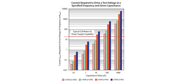
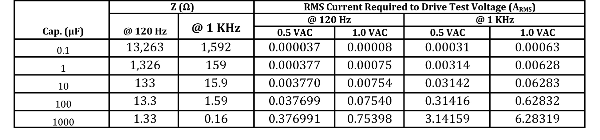
What happens when you attempt to measure a high value MLCC with an LCR tester not suited (i.e.- it does not have and adequate power supply to provide the DUT the with the necessary rms test voltage) for measuring high value MLCC’s with low Z and ESR? Answer: The tester will not supply the necessary AC test voltage and it will drop below a minimum specified level to provide the DUT with enough AC test voltage giving you an artificially low capacitance reading and leading you to believe that the capacitors are out of specification. You may set the test voltage to 1.0 V but many testers will not provide the true “selected” voltage and the actual test voltage applied to the DUT will probably be in the 0.3V-0.7V range due to the low impedance. Following is a graph of a table I supplied in the previous post on this subject showing capacitor impedance at 120Hz and 1kHz and the current required to the test voltage (Arms):
.png?width=1276&height=1545&name=figure1-post3%20(1).png)
This graph from the previous data supplied reveals that the test voltage may be reduced from 1.0V AC to 0.5 V AC which will further extend the capability of a capacitance meter with regard to AC test voltage. One of the question I have heard is: Why do most manufacturers specify a test frequency of 120Hz and a test voltage of 0.5V AC above 10uF but specify 1KHz for 10uF and below? The answer is typically known to be from the fact that Tantalum capacitors were specified to be measured at 120Hz and 0.5V so therefore the specification for higher value MLCC’s ( >10uF) were also measured at the same and lower test frequency and Voltage.
The use of 0.5V AC test voltage instead of 1.0V may enable a more accurate measurement of capacitance for values over 10uF such as the 22uF, 33uF(not as commonly made or utilized in our industry), 47uF , 100uF, 150uF, and the 220uF which is highest value MLCC in our industry in a 1210 package. This is especially the case when the LCR meter only has an AC current capability of 20mArms as by the red dotted line in the presented graph. Some LCR testers have enhanced current capability that may deliver up to 200m Arms which will be more effective in obtaining accurate capacitance measurements when values exceed 10uF and above.
In the next bog and final of the series of 4, I will make a recommendation on testing what I consider the unique value on in our industry, the 10uF. So as a precursor, the 10uF has a test specification of 1KHz and 0.5Vrms but a 12uF or 15uF has a test frequency and voltage of 1.0V rms and 1KHz. So in a span of 2uF’s, you change it while the layer count will not increase proportionately to its value or build up of active area within the capacitor. We will discuss and summarize the results in the next blog so until then, happy specification investigating and problem solving!
Until next time…
Nathan
.jpg?width=600&height=587&name=figure1---z-vs-freq-of-mlcc%20(1).jpg)


