
Greetings designers! So, you just finished your latest circuit design and you are amazed that you were able to find MLCCs that were smaller than the ones recommended by your power supply vendor. Your circuit footprint is now smaller and the total components cost is less. Congratulations! Give yourself a “high five” for your accomplishment!
No High Five for You!
The next week your design “crashes” during evaluation, due to excessive voltage drop, or to out of spec. ripple, or to… You ask yourself, “What happened?” You used the same capacitor values with the same “dielectric” that the power supply vendor recommended (“X5R”…whatever that is). Heck, you even used the same voltage rating that they recommended. What could have happened? Does size really matter that much?
Well, while you thought that the power supply specification was just old, and not up to date with the latest miniaturized capacitor offerings, it may be that the power supply vendor actually was current and was looking out for you, having tested their design recommendations (and perhaps others that didn’t work as well) prior to publication.
Not Your Father’s Capacitor
You see, not all X5R dielectrics and MLCC designs are the same. The X5R specification simply indicates an “envelope” that the dielectric will stay within throughout the temperature range between -55C to +85C (i.e., ≤+/-15% deviation in capacitance (typically measured at 1 VAC@1 KHz and 0VDC), relative to the “room temperature” capacitance (typically measured at either 20C or 25C)). It also indicates that it meets some type of reliability specification (which varies from manufacturer to manufacturer and with voltage rating) at 85C temperature and at rated voltage (or a multiple of rated voltage). Unfortunately, the specification does not cover allowable variation in capacitance with applied DC voltage, which can be quite considerable, and can vary greatly depending upon the chemical composition of the dielectric as well as the MLCC design. The reasons for this are based primarily in the chemistry of the ferroelectric dielectric materials used in the Type 2 MLCC, as well as in the MLCC design (primarily dielectric thickness) of the capacitor. Venkel recently published an excellent technical paper (link) that discusses the detail behind these reasons.
With progress in MLCC development (more capacitance in a smaller package), MLCC manufacturers have moved the boundaries of performance in order to meet the specifications that they have to meet (e.g., primarily X5R or other temperature characteristic, as well as specified reliability). In some cases, that has resulted in compromise of other factors (e.g., sensitivity of capacitance to voltage in this case). Small “tweaks” in dielectric chemistry or MLCC design, introduced with each new generation of MLCC, can have significant influence on these other factors (such as capacitance sensitivity to voltage). Not wanting to “air their dirty laundry” some manufacturers have been reluctant to publish these data, in some cases, to the detriment of their customers.
This Could Happen to You
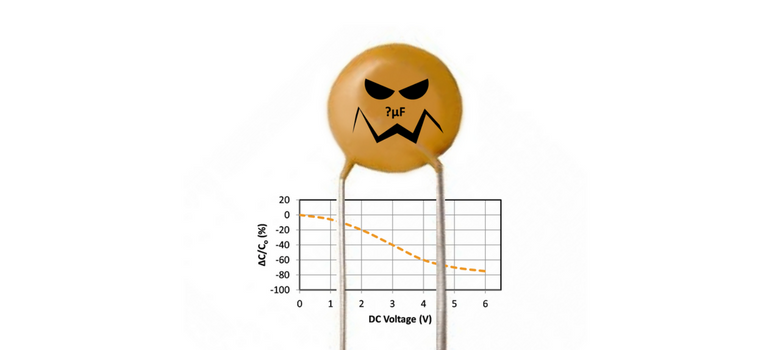
As a result some circuit designers have been “blindsided” when selecting MLCCs for their designs. For example, capacitance can decrease as much as 80% or 90% when rated voltage (DC) is applied as compared to the 0VDC applied voltage in the manufacturer’s specification. Imagine purchasing a 10µF 0402 MLCC and finding that it is really a 1µF capacitor at rated voltage, and ask yourself can your designs withstand that much change in capacitance? If so, fine. If not, you should choose a different capacitor.
In order to make an informed decision, look at the voltage sensitivity curve for the device you are interested in (link for examples). If you cannot accept the variation indicated in your design, look at the voltage sensitivity of other capacitors (higher voltage rating, larger case size, or less sensitive dielectric, or higher capacitance value, or the like) until you find a suitable solution to your design needs. Whatever you do don’t assume that Type 2 MLCCs have stable capacitance with respect to applied voltage, because typically, they don’t.
Parting Shots
So go forth and prosper using the best and most economical capacitor solution that you can find to meet the needs of your designs. Just be sure to “read the fine print” with regard to the performance aspects that are important to you. If the data that you need aren’t available, be sure to ask for it (http://www.venkel.com/technical/electrical-characteristics-data). The last thing that you want is to have your circuit fail in performance testing because of your improper selection of a sub-penny component. Now redesign that circuit, test it and give yourself that “high five!


