Celebrating 30 years.

Resource Center

Articles, datasheets, technical data, cross reference guides and more. All in one place.

Articles

Chip Resistors Part 2: Types

Posted by Mike Randall on November 17, 2014

4

This is Part 2 of a Three Part Series

  • Chip Resistors Part 1: The Basics
  • Chip Resistors Part 2: Types
  • Chip Resistors Part 3: Applications and Considerations


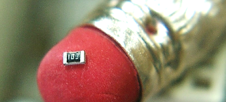
Greetings designers!  “A resistor by any other name” still resists current, right?  Of course, you know by now that the answer is, “it depends.”  What is the intended purpose and application environment for the resistor you seek?  What values, tolerances, temperature stabilities and other specifics are required?  What size can you accommodate and how much power will said resistor have to tolerate?  What other environmental factors (e.g., RoHS, high sulfur atmosphere, or the like) are important to your application?  To that end let’s talk about some different types of chip resistors.  We’ll discuss general purpose, high precision, current sense, high voltage, high power, high resistance, trimmable and environmentally compliant and chemically stable flavors of resistors.

General Purpose

General purpose chip resistors are used in surface mount circuit designs wherever you need a standard or general resistor such as for voltage reduction, current control, or the like.  These are typically thick film resistors, and are available in case sizes as small as 01005 (EIA).  General purpose chip resistors exhibit temperature coefficient of resistance (TCR) values as low as +/-100 ppm/C, with operating temperature range from -55C to 150C+, and have nominal values from as low as 0 Ω to 20 MΩ+, with power ratings ranging from ~0.01W to 2W+.

High Precision

High precision chip resistors are available in either thick film or thin film configurations.  They typically exhibit very low change in resistance with changing temperature.  Temperature coefficient of resistance (TCR) values for high precision chip resistors may be as low as +/-5 ppm/C.  Resistance tolerances are also very tight relative to standard chip resistors.  For example ultra high precision chip resistors may have resistor value tolerances as tight as +/-0.01%.  These resistors are useful when you can’t trim or calibrate your circuit post assembly, or in other circumstances where tight tolerances and high levels of resistor value stability with changing temperature are required.

Current Sense

Current sensors are circuits that detect and convert current to voltage that is proportional to the amount of current traversing the circuit.  Current sensing resistors are common for this purpose.  They create a voltage drop when voltage is measured across the resistor.  This voltage drop is directly related to the current via Ohm’s law (V=IR).  The resistance is carefully selected so as to cause a voltage drop suitable to the circuit when passing currents in the range anticipated by the design.  Current sense resistors are typically low value (<1 Ω) in order to avoid excessive power usage.  Further current sense resistor information is available via Venkel’s Current Sense Resistors Cheat Sheet.

High Voltage

Got a high voltage circuit for lighting or HV instrumentation or HV industrial or other HV applications?  As with HVMLCCs, high voltage chip resistors are likely needed.  These devices are designed to prevent arcing or voltage related failure in circuits rated up to 2KV.   

High Power

If you have an application requiring enhanced reliability or requiring high power density, you should consider using high power resistors in your design.   High power resistors utilize special materials and designs to improve thermal properties in order to provide better power dissipation capability.  High power resistors may be used in place of general purpose resistors where high power density is needed as they offer higher power ratings than their general purpose chip resistor analogs in the same case size.  They are well-suited for applications subjected to high current, or where a large de-rating margin is needed such as in high temperature environments or high power density applications or the like.

High Resistance

High resistance chip resistors are typically used in high impedance instruments, test equipment circuits, temperature measurement circuits, voltage dividers, circuits for gain setting, or other high impedance amplifier circuits or the like.  High resistance chip resistors are typically thick film resistors ranging in case size from 0402 (EIA) to 2512 (EIA) or larger.  Resistance values for these applications typically range from as low as 1 MΩ to 100GΩ+.

Trimmable Resistors

As a continuation of the “it depends” mantra, some circuit designs require at least one tunable or trimmable resistor as you just can’t “design-in” the optimal value until you actually test the circuit.  Devices using circuits that require calibration such as certain Op Amps, oscillators, voltage dividers, tuned sensor circuits and the like may benefit from use of trimmable resistors.  Trimmable resistors can be LASER trimmed to higher resistance than nominal as the resistor element and the glass passivation utilized are specially designed to allow in-situ LASER trimming after mounting the resistor to the circuit.  This enables in-situ tuning of the circuit.  In certain cases, trimmable resistors may even replace more costly and clumsy potentiometers as well.

Environmental Issues

We all care about our environment, and to that end RoHS (restriction of hazardous substances) regulations have resulted in the reduction or elimination of lead, mercury, cadmium hexavalent chromium, brominated biphenyls and diphenyl ethers from electronic components and equipment, chip resistors included.  In some cases, Pb is still allowed as a constituent (i.e., RoHS 5 or 5/6), but in many cases RoHS 6 or 6/6 is required.  The demand for the latter is likely to increase in the future as environmental regulations and requirements further mature.

Do you have problems with sulfur in your application atmosphere?  Certain materials, such as silver or copper tend to react with atmospheric sulfur creating corrosion that can become a major problem.  Care in materials selection and resistor design can help avoid this problem.  Anti–sulfuration resistors increase the reliability of chip resistors in sulfuric or otherwise contaminated environments such as experiences with certain industrial atmospheres, or with in-tire electronics or the like, where reaction with sulfur at the resistor element-termination interface can result in increased resistance due to formation of silver sulfide at that interface.  This can occur with as little as 1-3 ppm sulfur concentration in the ambient.  Anti-sulfuration resistors have been proven to prevent these types of failures.

Wow!…I hope that you agree that there are lots of “flavors” of chip resistors out there and I hope that this article will be helpful to you when selecting chip resistors for your circuit designs.  As with other components, it is critical to understand the temperature range and other environmental factors of your application as well as the voltages, power dissipations, resistance values, tolerances and other key requirements of the components that you select for your application.  My apologies to all of you Shakespeare lovers out there for butchering the prose of “The Master,” whether you be Capulet or Montague!  ;- )   TTFN!

Tags: Thin Film, Thick Film, general purpose chip resistor, tcr, High precision chip resistors

The Chip Resistors Part 1: The Basics

Posted by Mike Randall on October 21, 2014

24

This is Part 1 of a Three Part Series

• Chip Resistors Part 1:  The Basics
• Chip Resistors Part 2:  Types
• Chip Resistors Part 3:  Applications and Considerations

Greetings designers, let’s talk about resistors.  Resistors impede current flow, both alternating and direct currents are impeded equally by perfect resistors.  The unit for resistance is Ohms (Ω), named after German physicist Georg Ohm.  An Ohm is defined as the amount of resistance required to create a voltage drop of 1 volt (V), when the current flow is 1 Ampere (A).  From a dimensional standpoint, an Ohm is defined as 

resistors-part-1---graph-1
m is meter 
  • Kg is Kilogram
  • s is second
  • C is Coulomb
  • J is Joule
  • S is Siemens
  • F is Farad
  • W is Watt


…whew!  Thanks Wikipedia!   ;-)

This is interesting as the Ohm may be described in many different terms including time, distance, mass, charge, energy, capacitance and power…oh yes and conductance (Siemens-1), quite a versatile unit indeed!

Resistance Defined
Now that we understand what Ohms are, let’s find out how resistance (R) is determined.  As shown in the figure below, the resistance to a current flowing between plane 1 and plane 2 is found by the relation

resistors-part-1---graph-2

  • This is bulk resistance, and the above relation can be further simplified if the conductor is broken into square segments (i.e., if W = L) as shown below.   In that case, resistance simplifies to ρ is the resistivity of the material through which the current traverses (units Ω-m)
  • L is the length that the current traverses between planes 1 and 2 (units m)
  • A is the cross-sectional area of the conductor through which the current traverses (the area of either plane 1 or plane 2 (units m2)


    resistors-part-1-2
resistors-part-1---graph-3
  • T is the thickness of the conductor through which the current traverses (units m)

In the above case, resistance simplifies to a value having units of Ohms per square (Ω/□), which is typically called “sheet resistance.”  Sheet resistance is a simplification of resistance and is useful to designers as it simplifies the process of resistor design.  

Chip Resistor Design
The device designed will typically have at least one resistor element.  The element is constant in thickness (T) with a geometry that is comprised of squares.  The width and thickness of the trace helps establish power rating as well as the number of squares possible in the trace for a given package size.  Thicker and wider squares typically result in the ability to carry more current and to handle more power, but the number of squares (and the resulting resistance per unit length) is reduced.  The designer will pick a material with a specific Ω/□ value in order to enable the design to achieve the intended nominal resistance. Further, in order to maximize the number of squares per unit area, a serpentine pattern of interconnected squares is generally used so that more resistance can be packed into a smaller area, making the best of circuit board “real estate.”  An example is shown below.  In this case, use of a serpentine pattern of squares enables almost 2X the resistance in the same lineal distance.
resistors-part-1-3

 The resistor pattern is deposited on to a substrate, typically comprised of an alumina-based ceramic.  However, other materials, such as silicon carbide, etc., may be used for high power applications or other applications.  The resistor pattern is connected to two terminals, typically one on each end of the device, in order to enable connection with the circuit board.  The resistor trace is then trimmed to meet nominal resistance as necessary, and the resistor trace is over-coated, marked and tested to create the finished product.  The resistor device is then connected to the circuit at the assembly facility via surface mount technology (SMT).

Thick and Thin Film Resistors
As mentioned in Chris Gutierrez’s recent blog post, the resistor pattern is typically established via one of two methods, so chip resistors are usually categorized as either thick film or thin film resistors based upon the deposition method used.   Chris’ post is an excellent discussion of the two technologies.  Additionally, thick film resistor technology benefits from relatively easy composition modification as modification of the resistor thick film “ink” (e.g., chemistry, glass content, dopants for TCR, etc. for the resistor trace) is easily accomplished, whereas it is relatively difficult to change the resistor composition using thin film technology.  Thick film resistor materials are generally based upon ruthenium oxide (RuO2) mixed with specialized glass formulations and other dopants to achieved desired properties during firing, while thin film resistors are generally based upon vapor deposited Nichrome and need not fired to achieve desired properties.  In contrast, thin film technology typically benefits from better deposit uniformity and more accurate patterning, so both have their advantages.

How They Are Made
The general resistor manufacturing process involves designing the device to fit resistance nominal and power rating in the package size of interest as described above.  Next, the resistor material is deposited on the substrate which is selected for mechanical strength as well as electrical and thermal properties.  The resistor element deposition is patterned, then adjusted to nominal, then over-coated and the individual resistor chips are singulated, then terminated, tested and packaged.  In the case of thick film resistors, the resistor trace chemistry is carefully selected to set Ω/□ as well as to adjust temperature coefficient of resistance (TCR) and other key properties, and the material is deposited and patterned in one step using screen or stencil printing.  The thick film resistor deposit is then thermal treated to achieve the electrical properties desired.  In the case of thin film resistors, the resistor material is first deposited to achieve a highly uniform thin film, and then patterned using photolithographic technics.  In the case of both technologies, the deposit thickness is carefully controlled to achieve the desired Ω/□, and the pattern is adjusted, typically via LASER ablation, to achieve the desired resistance (nominal).  The resistor pattern may also be adjusted for high voltage applications, or other specialized applications.  The thickness and the pattern uniformity of thick film resistor elements is typically much thicker and less uniform for thick film resistors in comparison to thin film resistors, making thin film resistors more desirable for certain applications (e.g., those involving, precision tolerances, high frequencies or the like).  

I hope that you found this useful…TTFN! 

Tags: Thin Film, Thick Film, Resistor, tcr, chip resistor

Thick Film vs. Thin Film Resistors

Posted by Chris Gutierrez on July 24, 2014

25

What’s the difference between Thin Film Resistors and Thick Film?

When looking at these two types of resistors side by side, they may appear to be similar. The main differences of these two products are the construction, thickness, and application usage of the resistive element itself (hence the descriptions of “thick” and “thin” film resistors). Thick film resistive elements are typically 10 ~ 50 uM in thickness, while thin films are 10 to 200 nM in thickness.  Thick films are applied using a very simple screening process while thin films use a much more sophisticated vacuum process technique that applies the element on a molecular level. Let’s take a look this in detail.

1. Construction

The base material of a thick film resistor element is a Ruthenium Oxide (RuO₂) paste that is screened onto a ceramic substrate.  After this process, the thick film resistors are then fired causing these layers to become glass-like which helps protect the resistive film and makes them less susceptible to failures due to the infiltration of moisture and other contaminants.  Thick film resistor processes can be referred to as an additive process; this means that it consists of layers (resistive element, protective coating, and electroplated terminations) added to the substrate. The thin film resistor element consists of a combination of nickel and chromium (also known as Nichrome) that is applied to a ceramic substrate using a high-voltage, vacuum sputtering process.  A serpentine pattern is then etched into the Ni/Cr element using a photolithographic process. An epoxy layer is screened onto the element to protect it from moisture and other contaminants. This thin film process can be referred to as a subtractive process, meaning unwanted material being etched away in the photo etching process.

2. Thickness
Both thick film and thin film resistors are laser trimmed to their final resistance value. But in general, thin films overall thickness is literally thinner because of the subtractive process. Keep in mind that thick and thin film resistors are also application specific. That is, the application and circuit design will determine what type of resistor is utilized. Thick film resistors are ideal for low cost, economical applications and are also better suited for higher power and high ohmic value requirements. Thin film resistors, on the other hand, offer tighter tolerances for precision applications.

3. Applications
Thin Film v. Thick Film Resistors

Tags: Thin Film, Thick Film, Resistor

Subscribe to Resource Center Updates