
This is Part 3 of a Three Part Series
- Part 1:It’s What’s Inside that Counts
- Part 2:Judging a Book by Its Cover:Don’t Forget the Outside
- Part 3:It Ain’t the Volts, It’s the Amps: Some Applications and Considerations
Now that we have discussed the internal design of high voltage MLCCs (HVMLCCs) as well as several factors regarding the outside of HVMLCCs and the surrounding circuity, let’s discuss some applications and considerations when using HVMLCCs. It is important to use the right HVMLCCs for your application. In general, HVMLCCs are used in numerous applications where high voltage (either AC or DC or both) are encountered. HVMLCCs are carefully designed to perform correctly via careful dielectric selection, internal and external design to prevent surface arcing through a “quasi-plasma” that may be established due to electric fields encountered in the related application. This corona discharge is to be avoided as it will degrade and possibly destroy the HVMLCC or the surrounding circuitry.
Overview: Actually, It’s the Volts and the Amps
The energy stored in a capacitor is related to the square of the voltage through the relationship:
where:
- E is energy in Joules
- C is capacitance in Farads
- V is voltage in Volts
Take away? Even though HVMLCCs typically have much lower capacitance values than standard MLCCs, they still can store about the same amount of energy at rated voltage.
Additionally, since the impedance of HVMLCCs can be quite low at high frequencies, it is important to understand the frequencies and voltages associated with your application. For example, if the impedance of the HVMLCC selected is low at a frequency utilized in your application, a great amount of current may be passed through the device at that frequency if the voltage associated with that frequency is high. In these situations, it is highly important to understand the current capacity (typically called ripple current capability) of the HVMLCC that you are thinking about selecting for your application; as use of a device with inadequate ripple current capability may result in overheating of the component, and damage to the component and the circuit. In the same context, it is important to understand the voltages that the HVMLCC you select will experience. This is especially important because HVMLCCs typically have low ESR values at relatively high frequencies. AC applications utilizing frequencies >10 KHz, or applications that may include voltage surges, are especially important to evaluate carefully, as most voltage ratings are based on DC voltages which may not be relevant at all to these situations.
For most relatively low frequency AC applications (i.e., less than ~10 KHz), it’s typically OK to select an HVMLCC having a VRated value that is about 2.8X that of the VRMS of the application. This is based upon the logic that VRated should be about the same as VP-P. At higher frequencies, as impedance decreases, this multiplier should increase. It is highly important for the designer to test the circuit to insure proper device selection for his or her specific application. Testing will also inform the designer of other issues such as piezoelectric buzzing, overheating or the like. In these cases, redesign of the circuit or selection of a more appropriate HVMLCC is in order prior to sending the design to production.
Applications
There are many applications for HVMLCCs. Many of these require specially rated or certified devices (e.g., applications requiring safety rated capacitors and the like). The designer should always be familiar with all applicable specifications; and should specify each HVMLCC device accordingly. With that said, let’s discuss some applications.
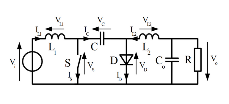
Power supplies are a major area of application. As an example, Cuk (pronounced “chook”) convertors are DC-DC convertors, invented by Slobodon Cuk, that use a capacitor for energy storage during the voltage conversion process. In this type of design, the voltage across the capacitor is typically:
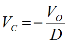
where:
- VC is the voltage across the capacitor
- VO is the output voltage
- D is the duty cycle
From the above, it is evident that, depending upon the output voltage and the duty cycle used, the voltage on the HVMLCC in the Cuk converter can be quite high.
HVMLCCs are also used in cold cathode fluorescent lamp (CCFL) driver circuits or lighting ballast circuits which typically require one or more HVMLCCs. High intensity discharge (HID) lamps also require similar boost-type power supplies which also require HVMLCCs. HVMLCCs are also used in certain high brightness light emitting diode (HBLED) driver circuits as well as in certain camera flash strobe circuits.
The take away here is that HVMLCCs are used in numerous switching power supply circuits for numerous applications. Other examples of this include snubber circuits in switch mode power supplies (SMPS) that reduce or eliminate voltage transients from MOSFET (metal oxide field effect transistor) switching events or the like, as well as resonator circuits, high voltage blocking circuits, high voltage coupling circuits, and input and output filter capacitors in power supply circuitry. These are all common power supply applications for HVMLCCs.
HVMLCCs are also used in general high voltage circuit applications, such as voltage multipliers, RF power circuits, and general applications requiring high voltage DC blocking or AC coupling. Additionally, HVMLCCs are used in general applications where voltage surge suppression is required such as LAN products, including but not limited to, LAN/WAN interfaces, Ethernet switches, and analog and digital modems. They may also be used for DC blocking in modems for tip and ring applications. HVMLCCs are becoming more popular in automotive applications as well, and are used in numerous telecommunications, medical and military/aerospace/space applications. This is especially true for the latter with the increasing popularity of “fly by wire” technology.
As HVMLCCs typically have very high insulation resistance (IR), they are also popular for use with high temperature semiconductors (e.g., silicon on insulator (SOI) or the like) and in elevated temperature applications, as well as in specialized test and diagnostic equipment. Finally, remember that HVMLCCs with floating electrode (FE) design are also an excellent choice when the device is to be used across a battery line or application that should not fail short.
Considerations
As mentioned in my previous post, it is very important that the HV circuit be properly designed in order to prevent surface arcing or corona discharge. This is even more important in space or low vacuum applications as the “quasi-plasma” becomes “real plasma” in vacuum, and corona discharge is more likely at lower voltages at the relatively low gas pressures encountered in space. There are numerous excellent HV design guides for HV circuit boards that cover the above, as well as many additional important topics related to HV circuit design and component selection. One particular favorite is the “HIGH VOLTAGE PRINTED CIRCUIT DESIGN & MANUFACTURING NOTEBOOK.”[1] It describes numerous “rules of thumb” and is an excellent resource for the HV circuit designer.
In summary, always be sure to choose the right HVMLCC for your application, considering all of the voltages, transients, and frequencies as well as ripple voltages/currents involved. It is also important to consider and comply with all applicable certification requirements and specification requirements. Be sure to design and to test your circuit carefully, and know that floating electrode (FE) HVMLCCs rarely fail short, and thus are good for battery line applications in addition to all of the HV applications noted above.


