This is Part 2 of a Three Part Series
- Part 1:It’s What’s Inside that Counts
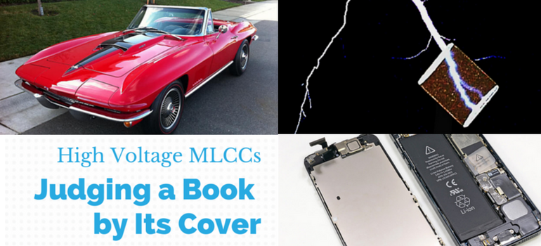
- Part 2:Judging a Book by Its Cover:Don’t Forget the Outside
- Part 3:It Ain’t the Volts, It’s the Amps:Some Applications and Considerations
Shhhhh! Don’t tell my Momma, but she wasn’t always right, and it isn’t only what’s inside that counts. Sometimes the outside is important too. If you are a car fan, you know what I’m talking about. For example, few auto enthusiasts salivate at the site of an AMC Pacer or Matador, but how many “jaws drop” at the site of a black-on-red ’67 Tri-Power ‘Vette or a ’69 Mach 1 big block with a shaker hood, or a shocking orange Hemi Superbird, or an original Lamborghini Countach or an Auburn Boattail Speedster, or…? I wouldn’t know personally, but I’ve been told that this also works with people too! J I’m not saying whether it’s wrong or right, but “it is what it is” (forgive me Momma!).
It’s What’s Outside that Counts Too
High voltage MLCCs can fail internally and we spent our last post discussing how to avoid that, but we didn’t talk about external arcing or any external-related failures. But it should be pretty simple, right? After all, the “MLCC thing” just looks like a brick with a metal cap on each end. How complicated can this be? Well, as it turns out, it’s not quite that simple. External failure usually results from at least one external arcing event, and that’s simple enough, but how does that arc get started and how might that arc repeat itself until device failure? There are several potential reasons and we will go through each.
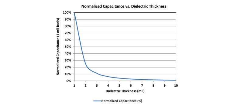
First, since HVMLCCs can be as small as 0603 (EIA) case size, it is important to control the minimum separation of the terminations. In the case of an 0603 (EIA), that is about 0.047” (~1.2 mm), so maximum voltage rating (~250 VDC) is limited compared to larger case MLCCs with larger termination separations (e.g., 1206 (EIA) with maximum VRated of ~3 KV having minimum termination separation of about 0.073” (~1.85 mm), and 1808 (EIA) with maximum VRated of ~5 KV, having a minimum termination separation of about 0.128” (~3.25 mm)).
Next, it is important to note that all surfaces (e.g., 4 sides) between the two external terminals must be clean in order to maximize surface resistance between the terminals, as contamination tends to be more conductive than ceramic dielectrics. Additionally, it is important that the external surfaces separating the two terminals are also dense and smooth, as porosity and surface roughness can trap contamination and have lower surface resistance.
It is also important to carefully design your circuit board so that the termination lands have maximized separation distance, and one must take care to avoid the use of solder fluxes that contain ionic species that could facilitate arcing beneath the chip, or on one or more of the sides of the chip during operation. Of course, any residues resulting from surface mount (SMT) activities should be removed as well. “OK, “Commander Obvious”[1]! Nothing too esoteric yet, where’s the complicated stuff” you say?
Touché! Well, did you know that surface arcing also depends upon ionization of the air immediately covering the surface of the area of the region that arcs,[2] and that the “quasi-plasma” that is formed in the air in that region that enables the arcing is affected by the electric field that is associated with the internal structure of the MLCC (i.e., electrode design)? And did you know that said “quasi-plasma” and associated electric field is affected by the dielectric constant (K) of material from which the arcing surface is made (i.e., Class 2 ceramic dielectrics, such as Y5V, X5R or X7R or the like have a higher propensity toward surface arcing at a given voltage than do Class 1 ceramic dielectrics such as C0G)? And did you know that any impurities in the “quasi-plasma” formed in the air near the surface of the component or on the surface of the component can be deposited on the surface during arcing, or converted in a manner that results in a lower resistance path between the two external terminals, thereby almost guaranteeing that the old adage that “lightening never strikes the same place twice” does not at all apply to HVMLCCs? In fact, continued multiple external arcing is not an uncommon failure mode for HVMLCCs. OK then, have some respect for “Commander Obvious.”
So, Repeat After “Commander Obvious”
What is outside also counts! It is important to properly design your circuit and terminal solder pads properly for high voltage. It is important to understand that external arcing is affected by several factors (some obvious, some not). Use of wider terminal separations and lower K dielectrics should be considered. Understand that sometimes it is necessary to use Class 2 dielectrics, and in that case X7R should be favored over X5R or Y5V dielectrics as they typically have higher K than X7R dielectrics (which would result in a higher surface field on the HVMLCC that may cause surface arcing at lower voltage than the lower K X7R). The surfaces of the HVMLCCs used should be dense, smooth and clean as well for HV applications. Sourcing your HVMLCCs from aquality vendor is recommended as they have knowledge of, and experience with, the above factors. Use of fluxes containing any residue during SMT operations should also be avoided and proper cleaning of the board after SMT may be required as well.
Finally, it may be beneficial to add a conformal coating over the surface of the HVMLCCs and/or other HV components to prevent surface arcing. The coating should have a high breakdown strength, combined with a high resistivity (surface and bulk), as well as high breakdown strength. Silicones tend to be ideal for this application. If something more mechanically rugged is needed, then an epoxy (typically difficult to rework) or a urethane (typically easier to rework) should be good. And, most important of all, if you tell my Momma about any of this, I swear, I will deny it!…TTFN!