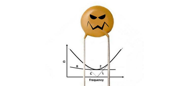
Equivalent series resistance or ESR is a measure used to characterize the real portion of the impedance of a capacitor. This is the resistance (R) that the impedance curve typically hits at series resonance, and ESR is commonly used to characterize that value. For a perfect capacitor ESR is 0. But, with the possible exception of CronutsTM, nothing is perfect, so we mortals must accept real capacitors.
At and near resonance frequency, ESR defines the impedance (Z) of a capacitor. At lower frequencies, impedance is largely controlled by capacitive reactance (XC) and at higher frequencies Z is controlled mainly by inductive reactance XL. Inductive reactance is controlled by inductance (L), and is commonly characterized by equivalent series inductance or ESL, in a manner analogous to using ESR for R. A typical model for a real capacitor at frequencies below and near resonance is a capacitor and a resistor in series as illustrated above.
Fun with Math
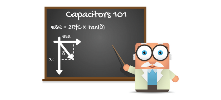
ESR is related to other performance measures of a capacitor as well. Dissipation factor or df is the measure of the ratio of a capacitor’s real resistance (ESR) to its capacitive reactance (XC). Df is equivalent to the tangent of the angle between ESR and XC as illustrated above. This angle is commonly called delta (δ) and so df = tan(δ). The cartoon above illustrates the geometry between XC, ESR and δ.
The inverse of df is the quality factor of a capacitor, also known as Q. So Q is a measure of the “perfectness” of a capacitor as Q=1/tan(δ). Since tan(δ) = ESR/XC, Q = XC/ESR. Following this logic, ESR = tan(δ)/XC = 2πfC·tan(δ) = 2πfC·df and the power dissipated by a capacitor at a given frequency near resonance is P = I2·Z ~ I2·ESR. So, as ESR is increased, the amount of power dissipated in the capacitor for a given current flow (I) increases.
What does all that mean?
So now that we know what ESR is and how it works, when should we select a capacitor with a higher ESR and when should we select a capacitor with a lower ESR? That seems obvious, right? We want to be as close to perfect with our capacitor as we can be, right? Not so fast my friends! Zero ESR, just like CronutsTM, may not always be your best choice in our real world.
When to Use Low ESR
There are situations where it is true that, lower ESR in the capacitor selected is better. For example in band pass or notch filtering, the high Q (and low ESR) of the device selected helps to increase the amount of signal passed over the range of frequency of interest while blocking signal outside of the frequency range of interest. In this case, the capacitance value is selected, in combination with the knowledge of the device’s inductance, in order to achieve resonance at the frequency of interest (f0), using the relation f0 = 0.1592·(L·C)-1/2 = 1/[2π√(L·C)]. Selection of the appropriate capacitor value will define a frequency “notch” wherein the impedance is suitable to pass current over a range of frequencies that is defined by its associated impedance curve. The edges of this frequency range are typically defined by a 3 decibel (dB) change in signal intensity from the base Z curve and the effectiveness of the filter is typically defined by the rate of change in passed frequency intensity with changing frequency, in units of decibel per decade of frequency or dB/decade. High Q and low ESR capacitors are used in these applications because the lower the ESR, the lower the impedance at resonance and the greater the amount of signal passed at f0 and the higher the dB/decade of the filter. As a definite and consistent frequency (f0) is needed for the circuit to filter properly, highly consistent capacitance values are needed as are consistent ESL and ESR, so that the filter will perform the same in all devices using the design. Because of this, it is prudent to use tight capacitance tolerance, low ESR NPO/C0G MLCCs for this application such as those available through Venkel. For this application, G (+/-2%) tolerance class or better C0G/NPO MLCCs are typically used.
In another application (when designing for power distribution over low-to-moderate frequencies), it is important to strive for a relatively flat impedance curve over a broad range of frequencies. Tantalum capacitors are ideal for this application and use of low ESR Ta capacitors can enable the use of lower part counts in achieving your “low and flat” Z goal. Such low ESR Ta capacitors are also available through Venkel. Another potential option for this application is selection of controlled ESR MLCCs, having increased ESR over standard MLCC designs. Controlled ESR MLCCs also typically have low ESL, making them ideal for applications requiring higher switching frequencies. Unfortunately, however, controlled ESR MLCCs are not generally available and they are typically very expensive. Because of these factors, low ESR Ta is still the capacitor of choice for this application. And if higher switching frequency is needed, standard configuration MLCCs or low ESL MLCCs are used in the power distribution network (PDN) to complement the low ESR Ta capacitors as needed.
When Low ESR can be a Problem
As with CronutsTM, it is possible however to “go too far” with low ESR, and the designer must be careful to avoid these situations. An example of this is when the ESR of the capacitor selected is very low and the range of application frequencies used in the design includes frequencies that are significantly higher than the series resonance frequency (f0) or SRF of the capacitor selected, such that parallel resonance occurs. When use frequencies exceed the parallel resonance frequency (PRF) of at least one capacitor in the circuit, a low ESR may not provide enough impedance to the resonating portion of the circuit in order to properly dampen the parallel resonance. In this case, a “tank oscillator” is established and the impedance curve may have sharp, resonance peaks, in direction opposite to the series resonance peak on the impedance curve, over the high frequency portion of the use frequency range of the impedance curve. This may result in unwanted behavior of the circuit, such as the introduction of noise to the circuit or the like. These phenomena are generally undesirable and may be addressed via proper capacitor selection, including proper selection of capacitance value, tolerance, and increased ESR values, such that parallel resonance is avoided, or at least dampened properly. Parallel resonance can also be avoided or reduced by mounting the high frequency MLCC(s) selected for you design onto your circuit in a manner such that the internal electrodes are oriented vertically. This, in effect, removes the odd harmonics of the parallel resonance of a capacitor, including the first harmonic, and increases the usable frequency range to below the second harmonic of the PRF.
In Conclusion:
So, we have discussed ESR and associated loss factors and we know that, generally, low ESR is good. We also know now that, for band pass and similar filtering situations, it is important to use tight tolerance, high Q, low ESR capacitors (NPO/C0G MLCCs) with consistent capacitance value, consistent ESR and consistent ESL. We also know that low ESR Ta capacitors are generally the capacitor of choice when designing for flat Z over a broad range of frequencies from low-to-intermediate frequencies for power distribution applications or the like. Finally we know to be careful to avoid deleterious effects of parallel resonance when selecting capacitors for high frequencies, and that we can do this through prudent capacitance value selection as well as use of moderate ESR MLCCs and/or making sure that the frequency range of our design does not encroach a PRF of any of the capacitors in the circuit. We also know that PRF can be increased by mounting the MLCC of interest with its internal electrodes oriented vertically so as to eliminate odd harmonics (including the first PRF harmonic).
Whew! That was exhausting…I need a CronutTM! TTFN!


