Hey circuit designers! Have you ever wondered why a circuit that you designed just didn’t act like you thought it should? Well, that could be due to many reasons; several of which may be related to the capacitors that you selected for your circuit. In this case you could be a victim of “deviant behavior”…behavior that differs from a norm or from accepted standards. In this case, the standards of interest would be those set by the mythical “perfect capacitor”…the Unicorn of passive electronics.
An Imperfect World
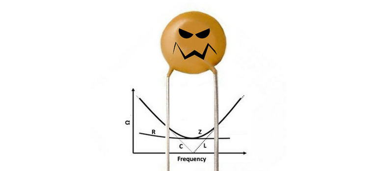
You see, like all electronic components, capacitors are not perfect. The type of capacitor that you select will determine how far from perfection, or deviant the capacitor’s performance will be in your application. Each real capacitor is a device that has not only a characteristic capacitance (C), but a characteristic resistance (R, typically termed equivalent series resistance or ESR) and an inductance (L, typically termed equivalent series inductance or ESL). These “parasitics” can adversely affect circuit performance, but in certain situations may be used to your advantage.
I remember how one of my sarcastic coworkers used to joke about “parasitics.” He would say, “Shoot! I don’t understand why our customers are so unhappy about parasitics; we ship them a free inductor and a free resistor with every capacitor!” J
Curves Ahead
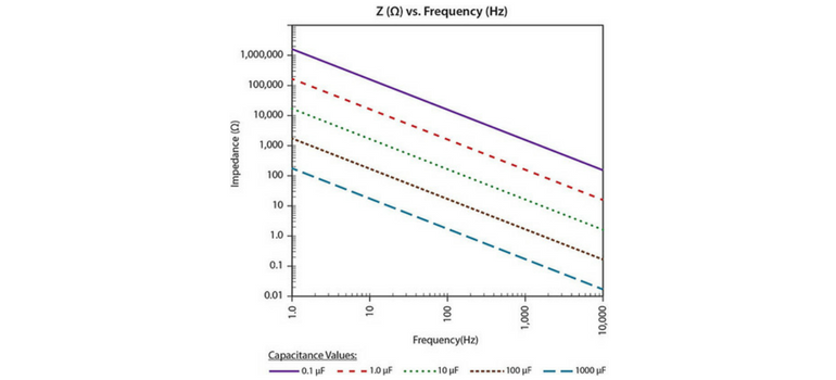
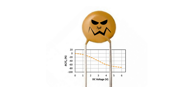
Simply put, parasitics affect impedance (Z) as frequency is changed (i.e., the “Z curve”), which may affect circuit performance. A perfect capacitor exhibits Z = 1/(2πfC) where f is frequency. As C is increased, Z is reduced in a manner that is linear on a log-log scale (see left side of graphic above). As f increases, Z of a perfect capacitor continues to decrease in this manner out to infinite frequency. With a real capacitor, however, C “runs into” either R (typically ESR) or L (ESL) as f is increased, establishing either a “flat” or a minimum in the impedance curve. If ESR is relatively low, L will largely determine this minimum and the Z curve will be V or gull wing shaped in the case of extremely low ESR. If ESR is relatively high, R will establish a “floor” or “flat” in the Z curve over a relatively broad range of f. At higher frequencies L dominates, as Z is ~2πfL, resulting in increasing Z as f is increased in a manner that is linear on a log-log scale (see right side of graphic above).
You Got to Know When to Hold’em…and Know When to Fold’em
Prudent selection of capacitor type may be useful in achieving a desirable Z curve for your application. For example, use of capacitors having moderate or high ESR, combined with low ESL, typically results in a relatively flat Z curve. This may be useful for power delivery designs such as power delivery networks (PDNs), as a relatively “flat” impedance curve is often desirable. Capacitors, such as controlled ESR reverse geometry or controlled ESR interdigitated capacitors (IDCs) or face down solid electrolyte tantalum (Ta) or low ESL solid electrolyte aluminum (Al) capacitors may be useful in these applications. On the other hand, use of capacitors having very low ESR combined with low L, may be useful for inline high pass filter designs or for designs requiring high speed decoupling. Discoidal ceramic capacitors are typically used for high pass filtering, and standard IDC or reverse geometry capacitors may be useful in filtering or high speed decoupling applications. More recently the design community has favored use of numerous, small case size MLCC in parallel for high speed decoupling designs, as these MLCCs have moderate-to-low ESL (L), take up little space and can be used local to the decoupled device, and are relatively inexpensive. Additionally, use of capacitors having very low ESR, combined with moderate-to-high L, may be useful in band pass filter designs. Standard MLCCs typically “fit the bill” here, and low loss (high Q), tight tolerance, type 1 dielectric capacitors such as C0G MLCC are typically used here for consistency in resonance frequency (the frequency at which C and L cross if R is 0 or is nearly 0).
A Little Help from Your Friends
Capacitor manufacturers spend significant development resources optimizing the above qualities for different applications. With regard to parasitics, it’s all about the design, the dielectrics and the electrodes. For example, in order to minimize ESR, MLCC developers will take advantage of high active layer counts and relatively thick electrodes. To maximize ESR in an MLCC, special electrode designs may be used in IDC MLCC or resistors may be put in series with other MLCC using specialized termination materials or the like. For low ESR, special low resistivity internal electrode materials, such as copper or specialized electrode designs may be used.
Get Real
All combined, these materials and design factors may be used alone, or in combination, to optimize the C, R and L properties of a given capacitor design for one or more specific application(s) requiring a characteristic impedance (Z) curve, making it important for circuit designers to model their circuits with the real (C, R, L and Z) properties of the capacitors selected for their designs. That way, you may be able to take advantage of that free resistor and inductor that is included with each capacitor! J (At the very least you will be able to compensate for their idiosyncraZies in your design). Next time we will discuss part 2 of Deviant Behavior, but as Winnie the Pooh would say, “Ta ta for now!” (TTFN :-))


.jpg?width=600&height=587&name=figure1---z-vs-freq-of-mlcc%20(1).jpg)


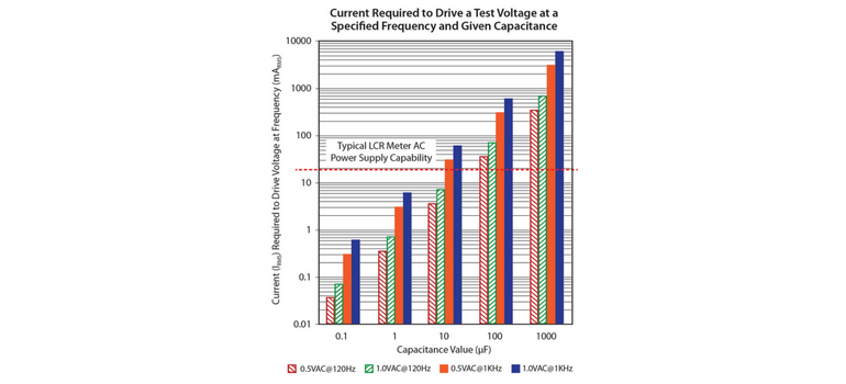
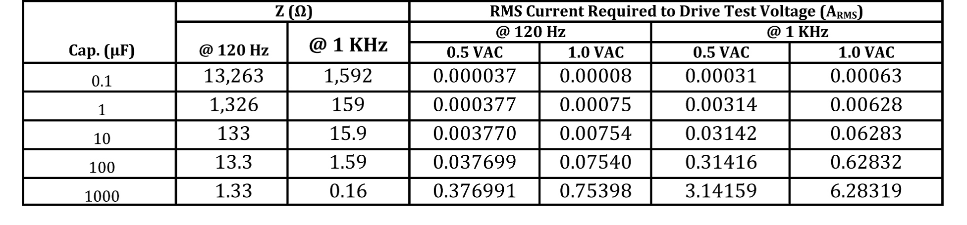
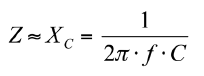 From this relationship, it is clear that the impedance of a capacitor is dependent upon frequency and capacitance value. So why does the electronic industry make a standard to measure a 10uF MLCC at 1KHz but a 15uF at 120Hz?
.png?width=500&name=Blogs%20de%20Datasheet%20images%20for%20Resource%20Center%20(2).png)