Celebrating 30 years.

Resource Center

Articles, datasheets, technical data, cross reference guides and more. All in one place.

Articles

High Voltage MLCCs: Shocking Revelations!

Posted by Mike Randall on September 25, 2014

18

This is Part 1 of a Three Part Series

  • Part 1:It’s What’s Inside that Counts
  • Part 2:Judging a Book by Its Cover:Don’t Forget the Outside
  • Part 3:It Ain’t the Volts, It’s the Amps:Some Applications and Considerations

Greetings fellow components users!  I hope that you have been well.  Have you ever had the need for a high voltage surface mount capacitor, but weren’t sure how to select the right one, or wondered how they are made, or were concerned about the factors you need to be careful of when designing them into your circuit?    In my next three posts, I will try to provide some “enlighteningment” on the subject. 

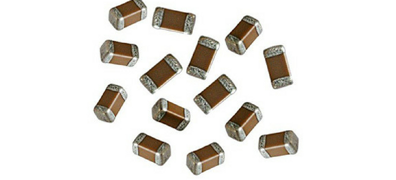
Surface mount high voltage MLCCs usually appear to be identical to standard MLCCs.   High voltage MLCCs are typically available in EIA size from 0603 to 2225 or larger with voltage ratings from 200V to 5,000V or more.  Smaller case high voltage MLCCs typically have lower maximum rated voltages (VRated) as the external terminals tend to be closer to each other in comparison to larger case high voltage MLCCs. 

High voltage MLCCs are generally available with Class 1 (C0G) or Class 2 (Ferroelectric X7R) ceramic dielectrics with tolerances as good as +/-5% or better, to as wide as +/-20% or higher.  Because of the generally thicker dielectric thicknesses used in the design and potentially the “cascade” or “floating electrode” type designs used, the maximum capacitance values available are significantly lower than analogous low voltage rated MLCCs.   Generally available capacitance values range from ~1 pF to 2.2 µF or higher.   The ESR is also typically a little higher compared to analogous standard MLCCs, but is still quite low (typically ≤10 mΩ).  So what makes high voltage MLCCs different from standard MLCCs?

The More Things Change, The More They Stay The Same

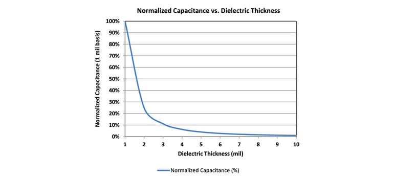
From the outside, high voltage MLCCs look pretty much identical to standard MLCCs, but as my Momma used to tell me, “it’s what’s inside that counts.”  It seems that it should be straight forward to design high voltage MLCCs.  Just increase the dielectric thickness (DT) to enable the desired voltage rating.  The rate of increase in DT is typically about 200 to 250 V/mil (or about 7.8 to 10 V/µm).  We also know that thicker DT results in less capacitance per unit volume (C/V), having a DT-2 relationship as shown in Figure 1 below.  So if we double DT, capacitance is quartered and VRated is doubled.  Simple…right?  Wait just a second!  As it turns out, it’s not quite that simple.

Figure 1.  Approximate normalized capacitance vs. dielectric thickness for standard configuration MLCC

VRated of the ceramic dielectrics used in MLCCs typically demonstrates linear or nearly linear behavior to voltages as high as ~1,000 to ~1,500 V.  But at higher voltages, a different VRated vs. dielectric thickness relationship is observed.  An example of this is given in Figure 2 below.

Figure 2.  Dielectric thickness vs. rated voltage for a typical ceramic dielectric used in MLCCs

For the hypothetical example given in Figure 2, a rated voltage of 1,500 V would require ~10 mil (~250 µm) DT.  This would reduce C/V by a factor of ~100 in comparison to a 250VRated, 1 mil DT MLCC!  If we could in some way maintain the initial linear relationship (~200 to 250 V/mil) we could have used DT of ~6 mil and C/V would have suffered only about a 35 fold reduction in comparison to a 250VRated, 1 mil DT device (i.e., the resulting maximum C/V would be almost 3 times as high in comparison to the case of 10 mil DT).   There must be a way to maintain this relationship, but how?

It’s What’s Inside That Counts

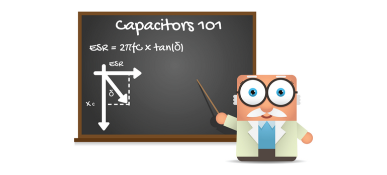
Well, it just so happens that there is a way.  Recalling our freshman EE course, we know that capacitors in parallel are additive, while in series behave in a manner defined by the relation:

We also know that, if all of the capacitors that are in series have the same capacitance value, the above simplifies to:*Cn = Capacitance of capacitor n

formula2
*n is the number of capacitors in series, each having capacitance value Cn
Also, voltage ratings of capacitors in series increase linearly following the relation: 

*n is the number of capacitors in series, each having voltage rating Vn

 Wow!  Using the above relationships, we can increase VRated linearly with a relatively small decrease in capacitance (~C/n).  If only we could fit multiple capacitors in series within a single MLCC…but how?  Well, the structure of a standard configuration MLCC puts multiple capacitors in parallel configuration, so why can’t a clever designer put several capacitors in series configuration, within an MLCC as well?  It just so happens that, long ago, a very clever MLCC designer did exactly that and these floating electrode or cascade electrode design MLCCs have been available for high voltage applications for decades.  Here’s to you, Mr./Mrs./Ms. Clever Designer!

The Details

The basic floating electrode (FE) or cascade electrode designs are illustrated in comparison to a standard electrode configuration design MLCC in Figure 3 below.  From the illustration it is evident that floating electrodes placed between externally connected electrodes result in 2 cascades (or capacitors) per each floating electrode segment used in the design.   One and two FE (or 2 and 4 cascade) designs are illustrated in the figure.  From the figures, we can also see that the electrode active area (A) is reduced with each cascade as well, but if we ignore the dimension of the additional internal margins, the active area is approximately halved for each floating electrode and the rated voltage increases linearly with each internal capacitor in series.

 Because of the reduction in A and the series effect described above, the resulting C/V (ignoring the additional internal margin areas created with each FE) is proportional to 1/n2 (where n is the number of cascades created).  This means that VRated can increase linearly as the number of FEs is increased, with a C/V penalty that is pretty much analogous to the C/V penalty experienced with a standard capacitor configuration MLCC that utilizes increased DT to achieve desired VRated in the linear region below ~1,000 to 1,500 V (i.e., according to the blue line in Figure 2 above).   So now we have a solution to our problem!

Additionally, FE designs largely reduce or eliminate the possibility of short-type failures.  This is because all of the cascades or internal capacitors must fail in order to create a short-type failure.  Thus failure due to flexure cracking or the like is largely mitigated in most cases.  This makes FE type MLCCs also quite valuable in performance critical applications such as across a battery line or the like.

Figure 3.  Illustration of standard vs. floating internal electrode configurations

The Particulars

We can use FE or cascade electrode design to increase VRated with minimized impact on C/V.  As each FE will have an additional margin area associated with it, the impact of additional margins on C/V in small case MLCCs (typically EIA 0603 and possibly 0805) may be prohibitive, but for larger MLCCs (e.g., EIA 1206 to 2225) the impact is relatively small.  As in Figure 4 below, C/V decreases commensurate with (1/2n2), where n is the number of FEs within the design.  VRated also increases with 2n as does ESR.  The effect on ESR is largely compensated however, as the two or more internal capacitors typically have more electrodes in each internal capacitor stack (N), and since the aspect ratio of said electrodes within each of the internal capacitors will have relatively wide and short electrodes, which results in relatively low ESR, so the actual increase in ESR is typically negligible in comparison to standard configuration MLCCs of similar VRated.  Since FE design results in MLCCs having at least two internal capacitors in series, each of the internal capacitors must short in order for the FE MLCC to have an internal short, which is highly unlikely, making FE MLCC highly desirable for applications that are sensitive to short-type failures.  Thus, in comparison to standard configuration MLCCs; with careful design, it is possible to achieve high VRated with minimal increase in ESR and decrease in C/V.  

Figure 4.  Effects of floating internal electrodes on capacitance, ESR and rated voltage

In Summary

Floating electrode (FE) or cascade internal electrode designs may be used to increase VRated of MLCCs with minimal impact on ESR and capacitance per unit volume (C/V) in comparison to standard configuration MLCCs.  Additionally, FE designs largely reduce or eliminate the possibility of short-type failures and thus are valuable in battery line and other critical applications.  For these reasons, floating electrode or cascade electrode designs are typically superior to standard configuration designs for high voltage applications.

Tags: High Voltage, Capacitors, Ceramic, MLCC

Venkel's New "Green" RoHS 6/6 Resistor

Posted by Nathan Bailey on September 16, 2014

27

Venkel Ltd. just released the new CRG – RoHS 6/6 “Green” resistor new product offering this month on September 3rd, 2014.  This new resistor series is a general purpose Thick Film Resistor.  It incorporates new construction materials whereby Lead in the glass and Lead Oxide in the resistive element is now eliminated.  The glass frit contained within the resistive element (RuO2) no longer contains any Lead or Lead oxide and will meet the RoHS 1000ppm or 0.1% threshold without taking the 7C-I exemption. 

This product is being produced and released in the industry due to the fact the 7C-I exemption will be expiring on approximately July 1, 2016. (There is a chance the 7C-I exemption could be delayed if enough companies request an extension and an extension is approved by the EU).
A new product data sheet along with material declarations and reliability data are now available on-line at www.venkel.com.  SGS or Interek material reporting validation data (verifying all the material compositions or MDS’s) will be forthcoming within the coming months and available by the end of the year.  Besides the material differences, there are differences in the resistance ranges and in the Temperature Coefficient of Resistance (TCR) when compared to Venkel’s CR series General Purpose Thick Film Resistors.  In some cases, depending on the size and value needed, the TCR may be higher.   The wattage ratings are considered industry standard such as the 0402 and 0603 which are rated at 1/16th Watt (0.0625W) and 1/10th Watt (0.10W) respectively. 
Although the exemption is not set to expire until July of 2016, numerous customers have requested that we have a complaint alternative available now.  Depending on each company’s situation, some must have a strategy in place in order to get new products tested, verified and released.  Many companies want to get ahead of the game on this mandate so no bottlenecks or delays will occur prior to or after the deadline. 
The new CRG series resistors are available now. This series enables you to have your products fully RoHS 6/6 (if that specific resistor product line was the only commodity preventing you from being fully RoHS 6/6 compliant). Please let us know if you have any questions regarding this new product release and if samples are needed for qualification purposes and we will do our best to accommodate you
 
Sincerely,
Nathan Bailey
 

Tags: CRG, Resistor, RoHS, thick, film, CR, RoHS 6/6

Capacitor ESR: It’s EaSieR than you think!

Posted by Mike Randall on August 20, 2014

1

Equivalent series resistance or ESR is a measure used to characterize the real portion of the impedance of a capacitor.  This is the resistance (R) that the impedance curve typically hits at series resonance, and ESR is commonly used to characterize that value.  For a perfect capacitor ESR is 0.  But, with the possible exception of CronutsTM, nothing is perfect, so we mortals must accept real capacitors. 

At and near resonance frequency, ESR defines the impedance (Z) of a capacitor.  At lower frequencies, impedance is largely controlled by capacitive reactance (XC) and at higher frequencies Z is controlled mainly by inductive reactance XL.  Inductive reactance is controlled by inductance (L), and is commonly characterized by equivalent series inductance or ESL, in a manner analogous to using ESR for R.  A typical model for a real capacitor at frequencies below and near resonance is a capacitor and a resistor in series as illustrated above.

Fun with Math

ESR is related to other performance measures of a capacitor as well.  Dissipation factor or df is the measure of the ratio of a capacitor’s real resistance (ESR) to its capacitive reactance (XC).  Df is equivalent to the tangent of the angle between ESR and XC as illustrated above.  This angle is commonly called delta (δ) and so df = tan(δ).  The cartoon above illustrates the geometry between XC, ESR and δ. 

The inverse of df is the quality factor of a capacitor, also known as Q.  So Q is a measure of the “perfectness” of a capacitor as Q=1/tan(δ).  Since tan(δ) = ESR/XC, Q = XC/ESR.  Following this logic, ESR = tan(δ)/XC = 2πfC·tan(δ) = 2πfC·df and the power dissipated by a capacitor at a given frequency near resonance is P = I2·Z ~ I2·ESR.  So, as ESR is increased, the amount of power dissipated in the capacitor for a given current flow (I) increases.

What does all that mean?

So now that we know what ESR is and how it works, when should we select a capacitor with a higher ESR and when should we select a capacitor with a lower ESR?  That seems obvious, right?  We want to be as close to perfect with our capacitor as we can be, right?  Not so fast my friends!  Zero ESR, just like CronutsTM, may not always be your best choice in our real world.   

When to Use Low ESR

There are situations where it is true that, lower ESR in the capacitor selected is better.  For example in band pass or notch filtering, the high Q (and low ESR) of the device selected helps to increase the amount of signal passed over the range of frequency of interest while blocking signal outside of the frequency range of interest.  In this case, the capacitance value is selected, in combination with the knowledge of the device’s inductance, in order to achieve resonance at the frequency of interest (f0), using the relation f0 = 0.1592·(L·C)-1/2 = 1/[2π√(L·C)].  Selection of the appropriate capacitor value will define a frequency “notch” wherein the impedance is suitable to pass current over a range of frequencies that is defined by its associated impedance curve.  The edges of this frequency range are typically defined by a 3 decibel (dB) change in signal intensity from the base Z curve and the effectiveness of the filter is typically defined by the rate of change in passed frequency intensity with changing frequency, in units of decibel per decade of frequency or dB/decade.  High Q and low ESR capacitors are used in these applications because the lower the ESR, the lower the impedance at resonance and the greater the amount of signal passed at f0 and the higher the dB/decade of the filter.   As a definite and consistent frequency (f0) is needed for the circuit to filter properly, highly consistent capacitance values are needed as are consistent ESL and ESR, so that the filter will perform the same in all devices using the design.  Because of this, it is prudent to use tight capacitance tolerance, low ESR NPO/C0G MLCCs for this application such as those available through Venkel.  For this application, G (+/-2%) tolerance class or better C0G/NPO MLCCs are typically used.

In another application (when designing for power distribution over low-to-moderate frequencies), it is important to strive for a relatively flat impedance curve over a broad range of frequencies.  Tantalum capacitors are ideal for this application and use of low ESR Ta capacitors can enable the use of lower part counts in achieving your “low and flat” Z goal.  Such low ESR Ta capacitors are also available through Venkel.  Another potential option for this application is selection of controlled ESR MLCCs, having increased ESR over standard MLCC designs.  Controlled ESR MLCCs also typically have low ESL, making them ideal for applications requiring higher switching frequencies.  Unfortunately, however, controlled ESR MLCCs are not generally available and they are typically very expensive.  Because of these factors, low ESR Ta is still the capacitor of choice for this application.  And if higher switching frequency is needed, standard configuration MLCCs or low ESL MLCCs are used in the power distribution network (PDN) to complement the low ESR Ta capacitors as needed.

When Low ESR can be a Problem

As with CronutsTM, it is possible however to “go too far” with low ESR, and the designer must be careful to avoid these situations.  An example of this is when the ESR of the capacitor selected is very low and the range of application frequencies used in the design includes frequencies that are significantly higher than the series resonance frequency (f0) or SRF of the capacitor selected, such that parallel resonance occurs.  When use frequencies exceed the parallel resonance frequency (PRF) of at least one capacitor in the circuit, a low ESR may not provide enough impedance to the resonating portion of the circuit in order to properly dampen the parallel resonance.  In this case, a “tank oscillator” is established and the impedance curve may have sharp, resonance peaks, in direction opposite to the series resonance peak on the impedance curve, over the high frequency portion of the use frequency range of the impedance curve.  This may result in unwanted behavior of the circuit, such as the introduction of noise to the circuit or the like.  These phenomena are generally undesirable and may be addressed via proper capacitor selection, including proper selection of capacitance value, tolerance, and increased ESR values, such that parallel resonance is avoided, or at least dampened properly.  Parallel resonance can also be avoided or reduced by mounting the high frequency MLCC(s) selected for you design onto your circuit in a manner such that the internal electrodes are oriented vertically.  This, in effect, removes the odd harmonics of the parallel resonance of a capacitor, including the first harmonic, and increases the usable frequency range to below the second harmonic of the PRF. 

In Conclusion:

So, we have discussed ESR and associated loss factors and we know that, generally, low ESR is good.  We also know now that, for band pass and similar filtering situations, it is important to use tight tolerance, high Q, low ESR capacitors (NPO/C0G MLCCs) with consistent capacitance value, consistent ESR and consistent ESL.  We also know that low ESR Ta capacitors are generally the capacitor of choice when designing for flat Z over a broad range of frequencies from low-to-intermediate frequencies for power distribution applications or the like.  Finally we know to be careful to avoid deleterious effects of parallel resonance when selecting capacitors for high frequencies, and that we can do this through prudent capacitance value selection as well as use of moderate ESR MLCCs and/or making sure that the frequency range of our design does not encroach a PRF of any of the capacitors in the circuit.  We also know that PRF can be increased by mounting the MLCC of interest with its internal electrodes oriented vertically so as to eliminate odd harmonics (including the first PRF harmonic). 

Whew!  That was exhausting…I need a CronutTM!  TTFN!

Tags: esr, capacitor, high-q, esl

Decoupling Part 2: Low ESL MLCCs

Posted by Mike Randall on August 14, 2014


10

This is Part 2 of a Two Part Series

In my last post we discussed some decoupling basics, including multilayer ceramic capacitors (MLCCs) for tier 1 (high speed) decoupling.  In this post we discuss MLCC options for low inductance (ESL).  I hope that you find it useful as it is a fascinating subject to me, but first, some history.

History of MLCCs for High Speed Decoupling

Prior to the 1980s almost all electronics used plated through hole technology (PTH).  All MLCCs used were of leaded configuration and ESL values were quite high (typically >2,000 picoHenry (pH)).  As microprocessor technology advanced to higher frequencies and greater complexity, the need for high speed decoupling was recognized.  In the 1970s IBM developed their thermal conduction module (TCM) which utilized the ceramic multichip module (MCM), both “blockbuster” technologies at the time.  The technology was highly advanced, including high speed microprocessor technology and multiple other advanced technologies.  One highly advanced technology utilized was the use of low inductance “LICA” capacitors as the tier 1 decoupling solution. 

Enter the LICA

In conjunction with AVX, IBM invented and developed one of the first designed-for-purpose low inductance MLCCs called the low inductance capacitor array (LICA).  This device exhibited world leading performance, having ESL values of 50 (pH) or less.  However, LICA was very expensive, and was technically complex, using controlled-collapse-chip-connection (C4) technology, as well as interdigitated terminals for inductance cancellation, as well as enhanced electrode design and geometry for low ESL.  Because of its technical complexity, only certain manufacturers could use it and it was not adopted universally.  Nevertheless, it was a very impressive product and if you have an IBM mainframe, chances are you have some LICAs. 

Enter RGC MLCCs

Even though LICA’s performance was quite impressive, its cost and complexity left an unmet need for a “poor mans’ low inductance capacitor.”  The market needed a relatively low cost MLCC that could be easily mounted using standard SMD equipment, materials and techniques.  Reverse geometry capacitors (RGCs) are MLCCs having reversed electrode aspect ratio geometry, and that were developed to provide a solution for this need.   Example RGCs are pictured above.  Using RGC MLCCs resulted in an ESL reduction of about 60% or more compared to analogous standard configuration MLCCs.  Relatively low in cost and requiring only minor circuit design modification, RGC MLCCs represented an excellent low cost, low ESL solution, and RGCs are still popular today for some applications. 

Enter the IDC

Later, AVX further fleshed-out its low inductance MLCC offering by inventing the interdigitated capacitor (IDC) which exhibited ESL values between that of RGC MLCCs and LICAs.  IDC required an intermediately complex mounting scheme (interdigitated mounting pads and complex via schemes, etc.), and was significantly more expensive than standard configuration MLCCs.  Even though it was complex and somewhat expensive, IDCs also enjoyed great success as they presented a solution with performance nearing LICA that did not require exotic surface mounting technology (C4 and the like).  Many millions of computer microprocessors were decoupled using IDCs, and IDCs are still popular for certain applications today.

Enter the KISS Principle

The low ESL market was still not satisfied by the above solutions however, and microprocessor manufacturers and their circuit designers kept looking for low ESL solutions that are simple and cheap.  Over the above time period, and as MLCC miniaturization efforts began, it came to the realization of designers that ESL values of large case size, standard configuration MLCCs are significantly higher than the ESL values exhibited by their smaller case “brethren.”  Using this knowledge, designers started designing with standard configuration MLCCs, using the smallest case size where acceptable capacitance values were generally available “on the cheap” (see A Farad on the Head of  Pin for Free for details). 

Since EIA 0402 and EIA 0201 standard configuration MLCCs exhibit ESLs that are on the order of 0612 IDCs, and since Class 2 dielectric versions are generally available in these case sizes with capacitance values as high as 10 µF and 1 µF for 0402 and 0201 sizes respectively, many designers have pursued the strategy of using standard small case MLCCs.  A further advantage of this approach is that it allows relatively simple, standard circuit designs.  This is also advantageous as small case standard configuration MLCCs are now generally available and are priced most competitively compared to other low ESL solutions.  Because of these advantages, this approach is now the generally accepted solution for high speed decoupling and is used in many, if not most, high speed decoupling applications today.

Enter “Other” Solutions

Over this time frame, other low ESL MLCC configurations have been realized as well, such as controlled ESR IDCs, interposer MLCCs and the like.  These solutions have also suffered from cost and complexity however, and the simple, low cost solution of using numerous small case, standard configuration MLCCs, combined with prudent circuit design (as discussed in Part 1 of this series) has become the prominent solution, with other configurations, such as RGC MLCC, generally being used in specialized designs that cannot utilize very small case size components.

Closing Thoughts

Although, as stated in Part 1 of this series, ESL is more important than capacitance for decoupling at high frequencies, it is still important to understand and compensate for the fact that the capacitance of Class 2 dielectric MLCCs may drop significantly when a DC voltage is applied (even with voltages as low as those used to power modern microprocessors).  An understanding of this phenomenon is provided in Venkel’s technical paper, “Testing and Measurement Practices of High Capacitance Ceramic Capacitors,” and is defined for MLCCs of interest in Venkel’s “Electrical Characteristics Data (ECD) for Ceramic Capacitors.”  Well, that’s it for MLCCs for high speed decoupling. My next post will cover ESR…TTFN!

Tags: Capacitors, Ceramic Capacitors, Low Inductance

RoHS Regulations Extend to Medical and other Applications

Posted by Chris Gutierrez on August 13, 2014

19

For those of you who are in the field of Medical applications, have you heard that RoHS has extended the scope to cover 8 medical devices along with 9 monitoring and control instrumentations? If you didn’t know, pay close attention because this is for you. If you did know, then congratulations!  You probably have everything under control and things are sailing smooth for you, or we hope things are going smooth for you!

As of July 22, 2014 the Restriction of the use of Hazardous Substances (RoHS) , was extended to Medical and Monitoring and control instruments. These devices were not previously required to comply with RoHS guidelines according to EU directive 2011/65/EU.

With this extension of RoHS now covering these medical devices it means that going forward you must comply with the regulations set by the EU. This could be a stressful time for those who may have delayed the process of adding suppliers to their AVL. If you were proactive as I mentioned above, as I assume all of you reading this were, then you’re standing in pretty good shape. If you are reactive then my friends you might not be having a great time right now. As compliance people it can be very difficult some times to stay up with all the changing regulations and guide lines.  I guess it’s the cost of trying to make the world a better place to live. It’s my opinion that the more and more electronics continue to be a bigger part of our lives the more the scopes of RoHS and other environmental compliance regulations will change and broaden.

Here is a list of the devices now included in abiding by all RoHS regulations.

  • Smoke detectors
  • Heating regulators
  • Cardiology
  • Thermostats
  • Measuring, weighing appliances for household or laboratory equipment
  • Other monitoring and control instruments used in industrial installations
  • Radiotherapy equipment
  • Dialysis
  • Pulmonary ventilators
  • Nuclear medicine
  • Analyzers
  • Freezers
  • Fertilizations tests
  • Appliances for detecting, preventing monitoring, treating alleviating illnesses, injury or disability
  • Laboratory equipment for in-vitro diagnosis (although this extension does not currently apply to in-vitro diagnostic devices until July 22, 2016)

If you manufacture any of these devices, take a look at our line-up of surface mount components. All Venkel products are fully compliant with current RoHS2 guidelines.


Tags: RoHS

Testing High Capacitance Multilayer Capacitors, Measurement, Accuracy – Part 3

Posted by Nathan Bailey on August 12, 2014

22 


This is Part 3 of a Four Part Series

Hello fellow engineers and circuit problem solvers. We have a lots going on ‘round here and as we keep adding important and relevant data to our website and catalog. Just like you, there is much more to do but we are well on our way and making improvements in many areas. This month’s blog is #3 in a series of 4 related blogs regarding the testing and best practices for testing high value or high capacitance MLCC’s. This month will blog will expand on the information we have discussed and the 4th in the series will end with a general summary of all the aforementioned best practices for testing these high value MLCC’s.

What happens when you attempt to measure a high value MLCC with an LCR tester not suited (i.e.- it does not have and adequate power supply to provide the DUT the with the necessary rms test voltage) for measuring high value MLCC’s with low Z and ESR? Answer: The tester will not supply the necessary AC test voltage and it will drop below a minimum specified level to provide the DUT with enough AC test voltage giving you an artificially low capacitance reading and leading you to believe that the capacitors are out of specification. You may set the test voltage to 1.0 V but many testers will not provide the true “selected” voltage and the actual test voltage applied to the DUT will probably be in the 0.3V-0.7V range due to the low impedance. Following is a graph of a table I supplied in the previous post on this subject showing capacitor impedance at 120Hz and 1kHz and the current required to the test voltage (Arms):


Table 1

figure1-post3 (1)


Figure 1

This graph from the previous data supplied reveals that the test voltage may be reduced from 1.0V AC to 0.5 V AC which will further extend the capability of a capacitance meter with regard to AC test voltage. One of the question I have heard is: Why do most manufacturers specify a test frequency of 120Hz and a test voltage of 0.5V AC above 10uF but specify 1KHz for 10uF and below? The answer is typically known to be from the fact that Tantalum capacitors were specified to be measured at 120Hz and 0.5V so therefore the specification for higher value MLCC’s ( >10uF) were also measured at the same and lower test frequency and Voltage.


The use of 0.5V AC test voltage instead of 1.0V may enable a more accurate measurement of capacitance for values over 10uF such as the 22uF, 33uF(not as commonly made or utilized in our industry), 47uF , 100uF, 150uF, and the 220uF which is highest value MLCC in our industry in a 1210 package. This is especially the case when the LCR meter only has an AC current capability of 20mArms as by the red dotted line in the presented graph. Some LCR testers have enhanced current capability that may deliver up to 200m Arms which will be more effective in obtaining accurate capacitance measurements when values exceed 10uF and above.


In the next bog and final of the series of 4, I will make a recommendation on testing what I consider the unique value on in our industry, the 10uF. So as a precursor, the 10uF has a test specification of 1KHz and 0.5Vrms but a 12uF or 15uF has a test frequency and voltage of 1.0V rms and 1KHz. So in a span of 2uF’s, you change it while the layer count will not increase proportionately to its value or build up of active area within the capacitor. We will discuss and summarize the results in the next blog so until then, happy specification investigating and problem solving!

Until next time…

Nathan

Tags: esr, lcr, capacitor, MLCC

Decoupling Part 1: The Basics

Posted by Mike Randall on August 07, 2014

10

This is Part 1 of a Two Part Series

  • Decoupling Part 1:The Basics
  • Decoupling Part 2:Low Inductance MLCCs

One of the largest uses of ceramic capacitors in the electronics industry is for decoupling.  Decoupling is commonly referred to as a methodology used to provide a localized source of electrical energy to a circuit in order to prevent unwanted changes to the supply voltage.  Decoupling is commonly used in power delivery circuits in an application that involves a relatively high switching load.  Typical examples include power supplies and microprocessors. 

What happens?

For example, when the switching demand becomes too high at a microprocessor, the supply voltage may “droop” or be reduced to a level that is unacceptably low for the “on” state of one or more switches within the microprocessor.  When this occurs, switch state errors can happen and the microprocessor may either crash or do something different than you asked it too.  In order to prevent this from happening, designers place decoupling capacitors local to the microprocessor from the power line to ground.  In this configuration, the decoupling capacitors charge to the supply voltage value during normal operation, while blocking DC power transfer to ground.  When the switching load at the microprocessor becomes high, the charged, local decoupling capacitors become local energy sources as the supply voltage begins to drop due to the high demand at the microprocessor.  These “little batteries” quickly supply charge to the supply power in order to ensure that the supply voltage is maintained during conditions of high load from the microprocessor.  In that manner, they “decouple” the microprocessor from the power supply.

So now that we know what decoupling is, what are some “rules of thumb” with regard to decoupling?  From the most basic standpoint, we want to ensure that enough charge is always available to the load and that it is available quickly enough to prevent unacceptable voltage droop (or unacceptable change in waveform) and we want to do this all in an economic manner.  But first we will cover some decoupling history in order to provide perspective.

History of Decoupling

Approaches to decoupling have changed over time.  Originally, multiple tiers of decoupling were used and the each tier decoupled into another tier closer to the load.  Typically very high value aluminum electrolytic capacitors would be used at the power supply which would serve to provide third tier decoupling to tantalum capacitors placed midway between the power supply and the microprocessor, which would provide second tier decoupling to ceramic capacitors placed near the microprocessor load, which provided first tier decoupling to the load or microprocessor.  While this methodology works well, it is relatively expensive and design engineers have spent considerable resources finding simpler schemes for decoupling.

As power supplies have evolved over time to higher switching frequencies, tier 3 and tier 2 have been reduced or combined or eliminated and an emphasis has been placed on power distribution quality of the power supply to tier 1 and the load over a broad range of frequencies.  Additionally, the evolution of microprocessors to include more on chip decoupling capacitance (tier 0) has somewhat reduced, the demands for tier 1 decoupling in general.  Additionally, microprocessor switching frequencies have largely stabilized over time due to power savings requirements as well as the advent of multicore microprocessors.  All of these factors have resulted in an evolution in decoupling that has enabled more economical, smaller, and generally better power distribution to a microprocessor (or switching load).

This leaves optimization of tier 1 decoupling.  The goal of Tier 1 decoupling is to feed enough charge to tier 0 decoupling capacitance, resident within the microprocessor quickly enough to prevent significant voltage droop or other signal degradation.  Multilayer ceramic capacitors (MLCCs), with their small size and low ESR (i.e., ability to discharge very quickly) are ideal for this application and as such are the capacitor of choice for this application. 

Some Guidelines

The amount of capacitance that you need will depend upon your situation (mostly switching speed and switching energy).  The effect of the combination of switching speed and switching energy upon voltage droop is characterized by the equation:      

where:
  • VDroop is voltage droop                  
  • I is current (Amperes)
  • ω is angular frequency (f) and is equal to 2πf
  • C is capacitance (Farads)
  • ESL is equivalent series inductance (Henries)
  • ESR is equivalent series resistance (Ohms)

Typically multiple MLCCs are placed locally in parallel in a decoupling design.  The values depend upon the situation with more capacitance being needed at lower frequencies and lower ESL being needed at higher frequencies.  In practice, several each of several different capacitance values are placed locally;  tier 3 capacitors near the power supply and the tier 1 capacitors near the switching load or microprocessor. 

As an example, the above equation may be used to estimate maximum voltage droop in the case of multiple 10µF, 1µF, and 0.1µF and 0.01µF may be placed near the microprocessor to ensure that voltage droop is less than a specified value over a range of frequencies of interest.  If 10 each of the above 10µF, 1µF, and 0.1µF MLCCs and 20 each of the 0.01µF MLCCs are used very close to a microprocessor that can pull 25A at 2V with no more than 5% voltage droop allowed, the above configuration could be used to keep voltage droop less than 5% over the range of 1 MHz to 100 MHz.  The tier 0 capacitance (on chip) would be used to keep voltage droop low at higher frequencies (up to ~ 3Ghz or more).

The Process

In practice, the designer will determine the impedance needed for his or her power distribution network design using the relation:

where: Z is impedance (Ohms)

The designer will also calculate the tier 3 capacitance needed to ensure that the voltage does not droop below the acceptable limit at lower frequencies using the relation:

where: Δtlf is the maximum allowable rise time for low frequency (sec)

The designer will also calculate the inductance that his or her design must stay below on the tier 1 side of the design using the relation:

lmax

where: Δthf is the minimum allowable rise time at highest frequency (sec)

 Other Considerations

All capacitors are placed in parallel in the circuit from power to ground.  When selecting capacitors for the lower frequency end of the spectrum (i.e., tier 3 and tier 2) the designer selects a combination of capacitors with high capacitance and low ESR in order to minimize VDroop.  When selecting capacitors for the high frequency end of the application, the designer selects a combination of capacitors having lower capacitance and minimal ESL such that the circuit stays below the maximum impedance allowed at the high end of the application frequency range. 

Since a broad array of capacitance values will be used, it is important to select a combination of C, ESL and ESR that ensures avoidance of sharp peaks in Z due to anti-resonances between the different capacitance values placed in parallel.  The designer will also take advantage of the multiple resonance frequencies that a broad of capacitance values affords in order to minimize Z over a broad spectrum.

Circuit Design Considerations

It is also important to remember that, for tier 1 decoupling, the rest of the decoupling circuit design is important as well, as inductance of the entire circuit must be minimized.  To achieve this, tier 1 MLCCs are generally placed as close as possible to or directly on the microprocessor package.  To further reduce inductance, tier 1 MLCC may be placed on the back of the microprocessor package, directly beneath the microprocessor die.  To further ensure that circuit inductance is minimized, the MLCC connection to the circuit board, as well as the power and ground interconnects, should be designed to minimize current loops (inductance) using special solder pad and via design and placement, as well as use of multiple vias per mount where prudent. 

To reduce tier 1 inductance even further, use of specially designed, low ESL MLCCs may be used.  That will be the subject covered in Part 2 of this series.  I hope that you found this valuable…TTFN!

Tags: Ceramic Capacitors, decoupling, capacitor

Thick Film vs. Thin Film Resistors

Posted by Chris Gutierrez on July 24, 2014

25

What’s the difference between Thin Film Resistors and Thick Film?

When looking at these two types of resistors side by side, they may appear to be similar. The main differences of these two products are the construction, thickness, and application usage of the resistive element itself (hence the descriptions of “thick” and “thin” film resistors). Thick film resistive elements are typically 10 ~ 50 uM in thickness, while thin films are 10 to 200 nM in thickness.  Thick films are applied using a very simple screening process while thin films use a much more sophisticated vacuum process technique that applies the element on a molecular level. Let’s take a look this in detail.

1. Construction

The base material of a thick film resistor element is a Ruthenium Oxide (RuO₂) paste that is screened onto a ceramic substrate.  After this process, the thick film resistors are then fired causing these layers to become glass-like which helps protect the resistive film and makes them less susceptible to failures due to the infiltration of moisture and other contaminants.  Thick film resistor processes can be referred to as an additive process; this means that it consists of layers (resistive element, protective coating, and electroplated terminations) added to the substrate. The thin film resistor element consists of a combination of nickel and chromium (also known as Nichrome) that is applied to a ceramic substrate using a high-voltage, vacuum sputtering process.  A serpentine pattern is then etched into the Ni/Cr element using a photolithographic process. An epoxy layer is screened onto the element to protect it from moisture and other contaminants. This thin film process can be referred to as a subtractive process, meaning unwanted material being etched away in the photo etching process.

2. Thickness
Both thick film and thin film resistors are laser trimmed to their final resistance value. But in general, thin films overall thickness is literally thinner because of the subtractive process. Keep in mind that thick and thin film resistors are also application specific. That is, the application and circuit design will determine what type of resistor is utilized. Thick film resistors are ideal for low cost, economical applications and are also better suited for higher power and high ohmic value requirements. Thin film resistors, on the other hand, offer tighter tolerances for precision applications.

3. Applications
Thin Film v. Thick Film Resistors

Tags: Thin Film, Thick Film, Resistor

Counterfeit Electronic Components

Posted by Chris Gutierrez on July 17, 2014

counterfeit

One of the concerns around the electronics industry that has grown throughout the years is, Counterfeit Electronic Components. This has become an issue because parts can appear to have a legitimate label from a known manufacture of electronic components and pass an initial inspection. You could in fact have a counterfeit component without knowing it. If you take a closer look you can see some differences of actual manufactured parts and counterfeited parts. Also, one other thing that has made it harder to detect is that legitimate manufactures can also produce counterfeit components. Which is why this has become a global epidemic.

How some legitimate manufacturers are counterfeiting

Manufacturers can have illegal shifts operating at the manufacturing plants. Meaning manufacturers can have an after-hours shift that use sub-standard materials and then be processed by unqualified technicians and engineers. When this occurs the sub-standard parts can be sold at a cheaper price because they used sub-standard materials and quality control. This can lead to all kinds of problems. During incoming inspection one cannot observe if they have received a cheaper or sub-standard material component.

If it can’t be identified as a counterfeit part at incoming inspection, then the parts are deemed good and allowed to go into the production process. The part may not fail during functional testing of the final product but parts could have a much reduced life expectancy than a genuine non counterfeit part. If this occurs it can lead to parts failing in the field generating much higher costs for analysis and rework, leaving headaches for everyone.

Other areas where problems can occur are during the reflow and mounting of the components. Counterfeit parts might display inferior wetting characteristics leading to soldering issues or they may fail electrically affecting other components around them.  

As a manufacturer it is hard to know if your parts are being counterfeited and sold in the industry. When counterfeit components began to become an issue Venkel implemented a way to help limit the effects of counterfeit components being passed off as Venkel product.

What is Venkel doing you ask?

Venkel generated a watermark on our label to help customers identify if a product is genuine Venkel product. This was implemented in late 2013. All Venkel products manufactured from that time forward should and will contain a watermark label.  

To learn more about how counterfeit components have affected the electronics industry, have a look at our Counterfeit Components Infographic. Topics covered:

  • Applications where counterfeit components can be found
  • Why are they a problem?
  • Top commonly counterfeited parts
  • How parts are counterfeited
  • How legitimate manufactures counterfeit
  • Top counterfeit markets
  • Avoidance strategies

Tags: venkel, components

Class 1 MLCC vs. Film Capacitors: And The Winner Is…

Posted by Mike Randall on July 15, 2014

7

So, from my last blog post, you are thinking that Class 1 dielectric MLCCs are the “bee’s knees” when it comes to capacitors.  And they are, (I promise…J).  “What about film capacitors?” you ask.  Excellent question!  Let’s explore this topic.

Ceramic versus Film Capacitors

As we have discussed, MLCCs (both Class 1 and Class 2) have advanced greatly with time.  I believe that the rate of advancement of Class 1 MLCC has been faster than that of film capacitors.  I believe that this disparity in advancement has progressed to the point that there is now a pretty clear winner for small case surface mount devices (EIA 1812 and below)…and that winner is…envelope please…COG MLCC.  “Based on what,” you ask?  Let’s explore some more.

What’s Important?

Let’s start with our “Farad on the Head of a Pin for Free” set of goals.  The two types of film capacitor dielectrics that we will use in the comparison are PPS (polyphenylene sulfide) and PEN (polyethylene naphthalate) as these are the most generally available film dielectrics in a surface mount small case configuration. The smallest generally available case size for C0G MLCC is EIA 01005 while the smallest generally available size for film caps is EIA 0603, so C0G MLCCs are available that are ~1/64th the volume of the smallest generally available surface mount film capacitor.  These smaller capacitors take up only ~1/16th of the board space of the larger film capacitors (solder pads not included).  From this standpoint, C0G clearly wins. 

Also, C0G MLCC wins when comparing the highest capacitance generally available at a given rated voltage within a given case size.  For example for EIA 0805 the maximum capacitance generally available in a C0G MLCC is 0.047µF at 25Vrated, and for film capacitors (PPS) it is 0.027µF and 10Vrated.  (Note that you can get metallized acrylic film capacitors in EIA 0805 case size with a maximum capacitance of 0.15µF at 25Vrated, but that type of film dielectric is much more temperature sensitive, and exhibits a much higher dissipation factor and dielectric absorption, as well as a more limited temperature range.  So these types of film dielectrics are more suitable in comparison of tantalum capacitors or Class 2 MLCC and are not a part of this analysis).  The above results are similar for other case sizes EIA 1812 and less as well.

Now for the cost part, comparable PPS film capacitors are typically more than 2X the price of C0G MLCC, and PEN film capacitors are generally more expensive than PPS film caps.  Again C0G MLCC clearly wins. 

Hot Stuff

Let’s compare thermal stability and robustness.  The use temperature range for C0G MLCC is generally -55C to +125C.  PPS has a similar range and PEN is generally -55C to +85C, but some PEN film caps are available having use temperature range as wide as -55C to +125C as well.  Additionally, C0G MLCCs are available for high temperature applications (up to 260C+), so the edge goes to C0G MLCC again. 

Regarding temperature stability of capacitance, C0G MLCC can vary in capacitance no more than +/-30 ppm/C from -55 to +125C as compared to the room temperature (RT) value.  Assuming that RT is 20C, would allow a change in capacitance of as much as ~0.3%.  While PEN cannot meet this criterion, PPS is close so we will call it a tie.  With regard to dissipation factor (df), PEN and PPS both increase with temperature to the point that df at 125C is ~0.4 to 0.5%.  C0G MLCC generally do not exhibit df in excess of 0.1%, but df is not specified at other than RT for G0G, so we will call this a tie as well. 

With regard to thermal robustness, C0G MLCCs generally do not require special reflow profiles for surface mounting as film capacitors do, so C0G MLCC wins here.  With regard to reliability at elevated temperature, C0G MLCCs are generally highly reliable as are film capacitors.  However, C0G MLCCs are generally available with higher voltage ratings at a given capacitance within a given case size.  Also, certain film capacitors can be susceptible to humidity at elevated temperature, so the edge goes to C0G MLCC here as well. 

Other Stuff

So what’s left?  Well, with regard to dielectric absorption or the percentage of capacitance that a capacitor recharges after charging to a certain voltage, and then quickly discharging, C0G MLCC at ~0.5% is slightly better than PEN film at ~0.8%, while PPS film, at ~0.02 to ~0.05%, is the clear winner.  However, unless you are designing a circuit that is highly susceptible to the effects of dielectric absorption, such as a sample and hold analog to digital convertor circuit, this really doesn’t matter much since, even though the PPS value for dielectric absorption is ultra-low, the C0G MLCC value is also quite low (comparing favorably to other films), so the benefit is not obviously applicable in all but a few circuits.  For example in a circuit that charges to 2.5V, then quickly discharges, a C0G MLCC would re-apply a voltage of not more than ~12.5mV to the circuit, while PPS film would not re-apply more than ~1.25mV…both very low values.

With regard to electrical noise generated from mechanical shock, C0G MLCCs have been shown to be superior to film capacitors as well [i].  With regard to resistance to board flexure, film capacitors are generally thought to be more robust, but this can be situation specific as board flexure can pull off external terminations in addition to, or in lieu of, flexure cracks.  This failure mode may be more prominent in film caps as the terminals may not adhere as well, depending upon the termination configuration, materials and application process.  Flex robust C0G MLCCs are also now available, so this is nearly “a wash” with a slight edge going to film caps. 

With regard to self-healing properties, film capacitors clearly win as MLCCs do not self-heal.  However, PPS and PEN have limited to very limited self-healing capabilities compared to other film dielectrics, so this “win” is not very significant.  With regard to solvent resistance, C0G MLCCs are generally superior to film caps as well. 

In Summary

So it is pretty evident that, for small case (EIA 1812 or less) surface mount applications, with few exceptions C0G MLCC are superior to film capacitors.  Additionally, C0G MLCC are considerably more cost effective.  A very good one page summary of the advantages and disadvantages of using NP0/C0G MLCCs versus Film Capacitors .  For the applications discussed above, I think that it is pretty clear that C0G MLCCs are preferable to surface mount film capacitors, so “Winner Winner, Chicken Dinner...COG MLCC.”  TTFN!  

________________________  

[i] X. Xu, et al., “Advances in Class-I C0G MLCC and SMD Film Capacitors,” CARTS USA, Newport Beach, CA, March 2008. 

Tags: tantalum, Ceramic, capacitor, Film Capacitors

Subscribe to Resource Center Updates