Celebrating 30 years.

Resource Center

Articles, datasheets, technical data, cross reference guides and more. All in one place.

Articles

Mike Randall

Mike Randall
Michael has a PhD in Materials Science and Engineering with specific expertise in ceramic capacitors and associated electronic materials and processing. Mike is VP Consulting for Almegacy LLC and is author on over 60 publications and presentations.
Find me on:

Recent Posts

Capacitor ESR: It’s EaSieR than you think!

Posted by Mike Randall on August 20, 2014

1

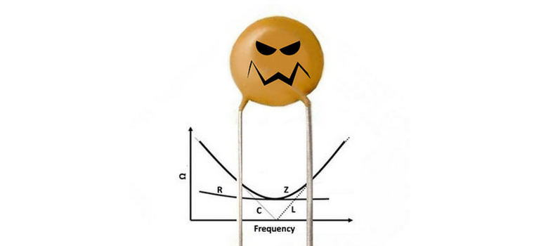
Equivalent series resistance or ESR is a measure used to characterize the real portion of the impedance of a capacitor.  This is the resistance (R) that the impedance curve typically hits at series resonance, and ESR is commonly used to characterize that value.  For a perfect capacitor ESR is 0.  But, with the possible exception of CronutsTM, nothing is perfect, so we mortals must accept real capacitors. 

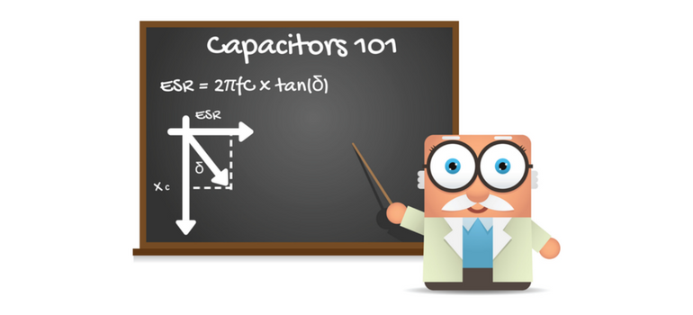
At and near resonance frequency, ESR defines the impedance (Z) of a capacitor.  At lower frequencies, impedance is largely controlled by capacitive reactance (XC) and at higher frequencies Z is controlled mainly by inductive reactance XL.  Inductive reactance is controlled by inductance (L), and is commonly characterized by equivalent series inductance or ESL, in a manner analogous to using ESR for R.  A typical model for a real capacitor at frequencies below and near resonance is a capacitor and a resistor in series as illustrated above.

Fun with Math

ESR is related to other performance measures of a capacitor as well.  Dissipation factor or df is the measure of the ratio of a capacitor’s real resistance (ESR) to its capacitive reactance (XC).  Df is equivalent to the tangent of the angle between ESR and XC as illustrated above.  This angle is commonly called delta (δ) and so df = tan(δ).  The cartoon above illustrates the geometry between XC, ESR and δ. 

The inverse of df is the quality factor of a capacitor, also known as Q.  So Q is a measure of the “perfectness” of a capacitor as Q=1/tan(δ).  Since tan(δ) = ESR/XC, Q = XC/ESR.  Following this logic, ESR = tan(δ)/XC = 2πfC·tan(δ) = 2πfC·df and the power dissipated by a capacitor at a given frequency near resonance is P = I2·Z ~ I2·ESR.  So, as ESR is increased, the amount of power dissipated in the capacitor for a given current flow (I) increases.

What does all that mean?

So now that we know what ESR is and how it works, when should we select a capacitor with a higher ESR and when should we select a capacitor with a lower ESR?  That seems obvious, right?  We want to be as close to perfect with our capacitor as we can be, right?  Not so fast my friends!  Zero ESR, just like CronutsTM, may not always be your best choice in our real world.   

When to Use Low ESR

There are situations where it is true that, lower ESR in the capacitor selected is better.  For example in band pass or notch filtering, the high Q (and low ESR) of the device selected helps to increase the amount of signal passed over the range of frequency of interest while blocking signal outside of the frequency range of interest.  In this case, the capacitance value is selected, in combination with the knowledge of the device’s inductance, in order to achieve resonance at the frequency of interest (f0), using the relation f0 = 0.1592·(L·C)-1/2 = 1/[2π√(L·C)].  Selection of the appropriate capacitor value will define a frequency “notch” wherein the impedance is suitable to pass current over a range of frequencies that is defined by its associated impedance curve.  The edges of this frequency range are typically defined by a 3 decibel (dB) change in signal intensity from the base Z curve and the effectiveness of the filter is typically defined by the rate of change in passed frequency intensity with changing frequency, in units of decibel per decade of frequency or dB/decade.  High Q and low ESR capacitors are used in these applications because the lower the ESR, the lower the impedance at resonance and the greater the amount of signal passed at f0 and the higher the dB/decade of the filter.   As a definite and consistent frequency (f0) is needed for the circuit to filter properly, highly consistent capacitance values are needed as are consistent ESL and ESR, so that the filter will perform the same in all devices using the design.  Because of this, it is prudent to use tight capacitance tolerance, low ESR NPO/C0G MLCCs for this application such as those available through Venkel.  For this application, G (+/-2%) tolerance class or better C0G/NPO MLCCs are typically used.

In another application (when designing for power distribution over low-to-moderate frequencies), it is important to strive for a relatively flat impedance curve over a broad range of frequencies.  Tantalum capacitors are ideal for this application and use of low ESR Ta capacitors can enable the use of lower part counts in achieving your “low and flat” Z goal.  Such low ESR Ta capacitors are also available through Venkel.  Another potential option for this application is selection of controlled ESR MLCCs, having increased ESR over standard MLCC designs.  Controlled ESR MLCCs also typically have low ESL, making them ideal for applications requiring higher switching frequencies.  Unfortunately, however, controlled ESR MLCCs are not generally available and they are typically very expensive.  Because of these factors, low ESR Ta is still the capacitor of choice for this application.  And if higher switching frequency is needed, standard configuration MLCCs or low ESL MLCCs are used in the power distribution network (PDN) to complement the low ESR Ta capacitors as needed.

When Low ESR can be a Problem

As with CronutsTM, it is possible however to “go too far” with low ESR, and the designer must be careful to avoid these situations.  An example of this is when the ESR of the capacitor selected is very low and the range of application frequencies used in the design includes frequencies that are significantly higher than the series resonance frequency (f0) or SRF of the capacitor selected, such that parallel resonance occurs.  When use frequencies exceed the parallel resonance frequency (PRF) of at least one capacitor in the circuit, a low ESR may not provide enough impedance to the resonating portion of the circuit in order to properly dampen the parallel resonance.  In this case, a “tank oscillator” is established and the impedance curve may have sharp, resonance peaks, in direction opposite to the series resonance peak on the impedance curve, over the high frequency portion of the use frequency range of the impedance curve.  This may result in unwanted behavior of the circuit, such as the introduction of noise to the circuit or the like.  These phenomena are generally undesirable and may be addressed via proper capacitor selection, including proper selection of capacitance value, tolerance, and increased ESR values, such that parallel resonance is avoided, or at least dampened properly.  Parallel resonance can also be avoided or reduced by mounting the high frequency MLCC(s) selected for you design onto your circuit in a manner such that the internal electrodes are oriented vertically.  This, in effect, removes the odd harmonics of the parallel resonance of a capacitor, including the first harmonic, and increases the usable frequency range to below the second harmonic of the PRF. 

In Conclusion:

So, we have discussed ESR and associated loss factors and we know that, generally, low ESR is good.  We also know now that, for band pass and similar filtering situations, it is important to use tight tolerance, high Q, low ESR capacitors (NPO/C0G MLCCs) with consistent capacitance value, consistent ESR and consistent ESL.  We also know that low ESR Ta capacitors are generally the capacitor of choice when designing for flat Z over a broad range of frequencies from low-to-intermediate frequencies for power distribution applications or the like.  Finally we know to be careful to avoid deleterious effects of parallel resonance when selecting capacitors for high frequencies, and that we can do this through prudent capacitance value selection as well as use of moderate ESR MLCCs and/or making sure that the frequency range of our design does not encroach a PRF of any of the capacitors in the circuit.  We also know that PRF can be increased by mounting the MLCC of interest with its internal electrodes oriented vertically so as to eliminate odd harmonics (including the first PRF harmonic). 

Whew!  That was exhausting…I need a CronutTM!  TTFN!

Tags: esr, capacitor, high-q, esl

Decoupling Part 2: Low ESL MLCCs

Posted by Mike Randall on August 14, 2014


10

This is Part 2 of a Two Part Series

In my last post we discussed some decoupling basics, including multilayer ceramic capacitors (MLCCs) for tier 1 (high speed) decoupling.  In this post we discuss MLCC options for low inductance (ESL).  I hope that you find it useful as it is a fascinating subject to me, but first, some history.

History of MLCCs for High Speed Decoupling

Prior to the 1980s almost all electronics used plated through hole technology (PTH).  All MLCCs used were of leaded configuration and ESL values were quite high (typically >2,000 picoHenry (pH)).  As microprocessor technology advanced to higher frequencies and greater complexity, the need for high speed decoupling was recognized.  In the 1970s IBM developed their thermal conduction module (TCM) which utilized the ceramic multichip module (MCM), both “blockbuster” technologies at the time.  The technology was highly advanced, including high speed microprocessor technology and multiple other advanced technologies.  One highly advanced technology utilized was the use of low inductance “LICA” capacitors as the tier 1 decoupling solution. 

Enter the LICA

In conjunction with AVX, IBM invented and developed one of the first designed-for-purpose low inductance MLCCs called the low inductance capacitor array (LICA).  This device exhibited world leading performance, having ESL values of 50 (pH) or less.  However, LICA was very expensive, and was technically complex, using controlled-collapse-chip-connection (C4) technology, as well as interdigitated terminals for inductance cancellation, as well as enhanced electrode design and geometry for low ESL.  Because of its technical complexity, only certain manufacturers could use it and it was not adopted universally.  Nevertheless, it was a very impressive product and if you have an IBM mainframe, chances are you have some LICAs. 

Enter RGC MLCCs

Even though LICA’s performance was quite impressive, its cost and complexity left an unmet need for a “poor mans’ low inductance capacitor.”  The market needed a relatively low cost MLCC that could be easily mounted using standard SMD equipment, materials and techniques.  Reverse geometry capacitors (RGCs) are MLCCs having reversed electrode aspect ratio geometry, and that were developed to provide a solution for this need.   Example RGCs are pictured above.  Using RGC MLCCs resulted in an ESL reduction of about 60% or more compared to analogous standard configuration MLCCs.  Relatively low in cost and requiring only minor circuit design modification, RGC MLCCs represented an excellent low cost, low ESL solution, and RGCs are still popular today for some applications. 

Enter the IDC

Later, AVX further fleshed-out its low inductance MLCC offering by inventing the interdigitated capacitor (IDC) which exhibited ESL values between that of RGC MLCCs and LICAs.  IDC required an intermediately complex mounting scheme (interdigitated mounting pads and complex via schemes, etc.), and was significantly more expensive than standard configuration MLCCs.  Even though it was complex and somewhat expensive, IDCs also enjoyed great success as they presented a solution with performance nearing LICA that did not require exotic surface mounting technology (C4 and the like).  Many millions of computer microprocessors were decoupled using IDCs, and IDCs are still popular for certain applications today.

Enter the KISS Principle

The low ESL market was still not satisfied by the above solutions however, and microprocessor manufacturers and their circuit designers kept looking for low ESL solutions that are simple and cheap.  Over the above time period, and as MLCC miniaturization efforts began, it came to the realization of designers that ESL values of large case size, standard configuration MLCCs are significantly higher than the ESL values exhibited by their smaller case “brethren.”  Using this knowledge, designers started designing with standard configuration MLCCs, using the smallest case size where acceptable capacitance values were generally available “on the cheap” (see A Farad on the Head of  Pin for Free for details). 

Since EIA 0402 and EIA 0201 standard configuration MLCCs exhibit ESLs that are on the order of 0612 IDCs, and since Class 2 dielectric versions are generally available in these case sizes with capacitance values as high as 10 µF and 1 µF for 0402 and 0201 sizes respectively, many designers have pursued the strategy of using standard small case MLCCs.  A further advantage of this approach is that it allows relatively simple, standard circuit designs.  This is also advantageous as small case standard configuration MLCCs are now generally available and are priced most competitively compared to other low ESL solutions.  Because of these advantages, this approach is now the generally accepted solution for high speed decoupling and is used in many, if not most, high speed decoupling applications today.

Enter “Other” Solutions

Over this time frame, other low ESL MLCC configurations have been realized as well, such as controlled ESR IDCs, interposer MLCCs and the like.  These solutions have also suffered from cost and complexity however, and the simple, low cost solution of using numerous small case, standard configuration MLCCs, combined with prudent circuit design (as discussed in Part 1 of this series) has become the prominent solution, with other configurations, such as RGC MLCC, generally being used in specialized designs that cannot utilize very small case size components.

Closing Thoughts

Although, as stated in Part 1 of this series, ESL is more important than capacitance for decoupling at high frequencies, it is still important to understand and compensate for the fact that the capacitance of Class 2 dielectric MLCCs may drop significantly when a DC voltage is applied (even with voltages as low as those used to power modern microprocessors).  An understanding of this phenomenon is provided in Venkel’s technical paper, “Testing and Measurement Practices of High Capacitance Ceramic Capacitors,” and is defined for MLCCs of interest in Venkel’s “Electrical Characteristics Data (ECD) for Ceramic Capacitors.”  Well, that’s it for MLCCs for high speed decoupling. My next post will cover ESR…TTFN!

Tags: Capacitors, Ceramic Capacitors, Low Inductance

Decoupling Part 1: The Basics

Posted by Mike Randall on August 07, 2014

10

This is Part 1 of a Two Part Series

  • Decoupling Part 1:The Basics
  • Decoupling Part 2:Low Inductance MLCCs

One of the largest uses of ceramic capacitors in the electronics industry is for decoupling.  Decoupling is commonly referred to as a methodology used to provide a localized source of electrical energy to a circuit in order to prevent unwanted changes to the supply voltage.  Decoupling is commonly used in power delivery circuits in an application that involves a relatively high switching load.  Typical examples include power supplies and microprocessors. 

What happens?

For example, when the switching demand becomes too high at a microprocessor, the supply voltage may “droop” or be reduced to a level that is unacceptably low for the “on” state of one or more switches within the microprocessor.  When this occurs, switch state errors can happen and the microprocessor may either crash or do something different than you asked it too.  In order to prevent this from happening, designers place decoupling capacitors local to the microprocessor from the power line to ground.  In this configuration, the decoupling capacitors charge to the supply voltage value during normal operation, while blocking DC power transfer to ground.  When the switching load at the microprocessor becomes high, the charged, local decoupling capacitors become local energy sources as the supply voltage begins to drop due to the high demand at the microprocessor.  These “little batteries” quickly supply charge to the supply power in order to ensure that the supply voltage is maintained during conditions of high load from the microprocessor.  In that manner, they “decouple” the microprocessor from the power supply.

So now that we know what decoupling is, what are some “rules of thumb” with regard to decoupling?  From the most basic standpoint, we want to ensure that enough charge is always available to the load and that it is available quickly enough to prevent unacceptable voltage droop (or unacceptable change in waveform) and we want to do this all in an economic manner.  But first we will cover some decoupling history in order to provide perspective.

History of Decoupling

Approaches to decoupling have changed over time.  Originally, multiple tiers of decoupling were used and the each tier decoupled into another tier closer to the load.  Typically very high value aluminum electrolytic capacitors would be used at the power supply which would serve to provide third tier decoupling to tantalum capacitors placed midway between the power supply and the microprocessor, which would provide second tier decoupling to ceramic capacitors placed near the microprocessor load, which provided first tier decoupling to the load or microprocessor.  While this methodology works well, it is relatively expensive and design engineers have spent considerable resources finding simpler schemes for decoupling.

As power supplies have evolved over time to higher switching frequencies, tier 3 and tier 2 have been reduced or combined or eliminated and an emphasis has been placed on power distribution quality of the power supply to tier 1 and the load over a broad range of frequencies.  Additionally, the evolution of microprocessors to include more on chip decoupling capacitance (tier 0) has somewhat reduced, the demands for tier 1 decoupling in general.  Additionally, microprocessor switching frequencies have largely stabilized over time due to power savings requirements as well as the advent of multicore microprocessors.  All of these factors have resulted in an evolution in decoupling that has enabled more economical, smaller, and generally better power distribution to a microprocessor (or switching load).

This leaves optimization of tier 1 decoupling.  The goal of Tier 1 decoupling is to feed enough charge to tier 0 decoupling capacitance, resident within the microprocessor quickly enough to prevent significant voltage droop or other signal degradation.  Multilayer ceramic capacitors (MLCCs), with their small size and low ESR (i.e., ability to discharge very quickly) are ideal for this application and as such are the capacitor of choice for this application. 

Some Guidelines

The amount of capacitance that you need will depend upon your situation (mostly switching speed and switching energy).  The effect of the combination of switching speed and switching energy upon voltage droop is characterized by the equation:      

where:
  • VDroop is voltage droop                  
  • I is current (Amperes)
  • ω is angular frequency (f) and is equal to 2πf
  • C is capacitance (Farads)
  • ESL is equivalent series inductance (Henries)
  • ESR is equivalent series resistance (Ohms)

Typically multiple MLCCs are placed locally in parallel in a decoupling design.  The values depend upon the situation with more capacitance being needed at lower frequencies and lower ESL being needed at higher frequencies.  In practice, several each of several different capacitance values are placed locally;  tier 3 capacitors near the power supply and the tier 1 capacitors near the switching load or microprocessor. 

As an example, the above equation may be used to estimate maximum voltage droop in the case of multiple 10µF, 1µF, and 0.1µF and 0.01µF may be placed near the microprocessor to ensure that voltage droop is less than a specified value over a range of frequencies of interest.  If 10 each of the above 10µF, 1µF, and 0.1µF MLCCs and 20 each of the 0.01µF MLCCs are used very close to a microprocessor that can pull 25A at 2V with no more than 5% voltage droop allowed, the above configuration could be used to keep voltage droop less than 5% over the range of 1 MHz to 100 MHz.  The tier 0 capacitance (on chip) would be used to keep voltage droop low at higher frequencies (up to ~ 3Ghz or more).

The Process

In practice, the designer will determine the impedance needed for his or her power distribution network design using the relation:

where: Z is impedance (Ohms)

The designer will also calculate the tier 3 capacitance needed to ensure that the voltage does not droop below the acceptable limit at lower frequencies using the relation:

where: Δtlf is the maximum allowable rise time for low frequency (sec)

The designer will also calculate the inductance that his or her design must stay below on the tier 1 side of the design using the relation:

lmax

where: Δthf is the minimum allowable rise time at highest frequency (sec)

 Other Considerations

All capacitors are placed in parallel in the circuit from power to ground.  When selecting capacitors for the lower frequency end of the spectrum (i.e., tier 3 and tier 2) the designer selects a combination of capacitors with high capacitance and low ESR in order to minimize VDroop.  When selecting capacitors for the high frequency end of the application, the designer selects a combination of capacitors having lower capacitance and minimal ESL such that the circuit stays below the maximum impedance allowed at the high end of the application frequency range. 

Since a broad array of capacitance values will be used, it is important to select a combination of C, ESL and ESR that ensures avoidance of sharp peaks in Z due to anti-resonances between the different capacitance values placed in parallel.  The designer will also take advantage of the multiple resonance frequencies that a broad of capacitance values affords in order to minimize Z over a broad spectrum.

Circuit Design Considerations

It is also important to remember that, for tier 1 decoupling, the rest of the decoupling circuit design is important as well, as inductance of the entire circuit must be minimized.  To achieve this, tier 1 MLCCs are generally placed as close as possible to or directly on the microprocessor package.  To further reduce inductance, tier 1 MLCC may be placed on the back of the microprocessor package, directly beneath the microprocessor die.  To further ensure that circuit inductance is minimized, the MLCC connection to the circuit board, as well as the power and ground interconnects, should be designed to minimize current loops (inductance) using special solder pad and via design and placement, as well as use of multiple vias per mount where prudent. 

To reduce tier 1 inductance even further, use of specially designed, low ESL MLCCs may be used.  That will be the subject covered in Part 2 of this series.  I hope that you found this valuable…TTFN!

Tags: Ceramic Capacitors, decoupling, capacitor

Class 1 MLCC vs. Film Capacitors: And The Winner Is…

Posted by Mike Randall on July 15, 2014

7

So, from my last blog post, you are thinking that Class 1 dielectric MLCCs are the “bee’s knees” when it comes to capacitors.  And they are, (I promise…J).  “What about film capacitors?” you ask.  Excellent question!  Let’s explore this topic.

Ceramic versus Film Capacitors

As we have discussed, MLCCs (both Class 1 and Class 2) have advanced greatly with time.  I believe that the rate of advancement of Class 1 MLCC has been faster than that of film capacitors.  I believe that this disparity in advancement has progressed to the point that there is now a pretty clear winner for small case surface mount devices (EIA 1812 and below)…and that winner is…envelope please…COG MLCC.  “Based on what,” you ask?  Let’s explore some more.

What’s Important?

Let’s start with our “Farad on the Head of a Pin for Free” set of goals.  The two types of film capacitor dielectrics that we will use in the comparison are PPS (polyphenylene sulfide) and PEN (polyethylene naphthalate) as these are the most generally available film dielectrics in a surface mount small case configuration. The smallest generally available case size for C0G MLCC is EIA 01005 while the smallest generally available size for film caps is EIA 0603, so C0G MLCCs are available that are ~1/64th the volume of the smallest generally available surface mount film capacitor.  These smaller capacitors take up only ~1/16th of the board space of the larger film capacitors (solder pads not included).  From this standpoint, C0G clearly wins. 

Also, C0G MLCC wins when comparing the highest capacitance generally available at a given rated voltage within a given case size.  For example for EIA 0805 the maximum capacitance generally available in a C0G MLCC is 0.047µF at 25Vrated, and for film capacitors (PPS) it is 0.027µF and 10Vrated.  (Note that you can get metallized acrylic film capacitors in EIA 0805 case size with a maximum capacitance of 0.15µF at 25Vrated, but that type of film dielectric is much more temperature sensitive, and exhibits a much higher dissipation factor and dielectric absorption, as well as a more limited temperature range.  So these types of film dielectrics are more suitable in comparison of tantalum capacitors or Class 2 MLCC and are not a part of this analysis).  The above results are similar for other case sizes EIA 1812 and less as well.

Now for the cost part, comparable PPS film capacitors are typically more than 2X the price of C0G MLCC, and PEN film capacitors are generally more expensive than PPS film caps.  Again C0G MLCC clearly wins. 

Hot Stuff

Let’s compare thermal stability and robustness.  The use temperature range for C0G MLCC is generally -55C to +125C.  PPS has a similar range and PEN is generally -55C to +85C, but some PEN film caps are available having use temperature range as wide as -55C to +125C as well.  Additionally, C0G MLCCs are available for high temperature applications (up to 260C+), so the edge goes to C0G MLCC again. 

Regarding temperature stability of capacitance, C0G MLCC can vary in capacitance no more than +/-30 ppm/C from -55 to +125C as compared to the room temperature (RT) value.  Assuming that RT is 20C, would allow a change in capacitance of as much as ~0.3%.  While PEN cannot meet this criterion, PPS is close so we will call it a tie.  With regard to dissipation factor (df), PEN and PPS both increase with temperature to the point that df at 125C is ~0.4 to 0.5%.  C0G MLCC generally do not exhibit df in excess of 0.1%, but df is not specified at other than RT for G0G, so we will call this a tie as well. 

With regard to thermal robustness, C0G MLCCs generally do not require special reflow profiles for surface mounting as film capacitors do, so C0G MLCC wins here.  With regard to reliability at elevated temperature, C0G MLCCs are generally highly reliable as are film capacitors.  However, C0G MLCCs are generally available with higher voltage ratings at a given capacitance within a given case size.  Also, certain film capacitors can be susceptible to humidity at elevated temperature, so the edge goes to C0G MLCC here as well. 

Other Stuff

So what’s left?  Well, with regard to dielectric absorption or the percentage of capacitance that a capacitor recharges after charging to a certain voltage, and then quickly discharging, C0G MLCC at ~0.5% is slightly better than PEN film at ~0.8%, while PPS film, at ~0.02 to ~0.05%, is the clear winner.  However, unless you are designing a circuit that is highly susceptible to the effects of dielectric absorption, such as a sample and hold analog to digital convertor circuit, this really doesn’t matter much since, even though the PPS value for dielectric absorption is ultra-low, the C0G MLCC value is also quite low (comparing favorably to other films), so the benefit is not obviously applicable in all but a few circuits.  For example in a circuit that charges to 2.5V, then quickly discharges, a C0G MLCC would re-apply a voltage of not more than ~12.5mV to the circuit, while PPS film would not re-apply more than ~1.25mV…both very low values.

With regard to electrical noise generated from mechanical shock, C0G MLCCs have been shown to be superior to film capacitors as well [i].  With regard to resistance to board flexure, film capacitors are generally thought to be more robust, but this can be situation specific as board flexure can pull off external terminations in addition to, or in lieu of, flexure cracks.  This failure mode may be more prominent in film caps as the terminals may not adhere as well, depending upon the termination configuration, materials and application process.  Flex robust C0G MLCCs are also now available, so this is nearly “a wash” with a slight edge going to film caps. 

With regard to self-healing properties, film capacitors clearly win as MLCCs do not self-heal.  However, PPS and PEN have limited to very limited self-healing capabilities compared to other film dielectrics, so this “win” is not very significant.  With regard to solvent resistance, C0G MLCCs are generally superior to film caps as well. 

In Summary

So it is pretty evident that, for small case (EIA 1812 or less) surface mount applications, with few exceptions C0G MLCC are superior to film capacitors.  Additionally, C0G MLCC are considerably more cost effective.  A very good one page summary of the advantages and disadvantages of using NP0/C0G MLCCs versus Film Capacitors .  For the applications discussed above, I think that it is pretty clear that C0G MLCCs are preferable to surface mount film capacitors, so “Winner Winner, Chicken Dinner...COG MLCC.”  TTFN!  

________________________  

[i] X. Xu, et al., “Advances in Class-I C0G MLCC and SMD Film Capacitors,” CARTS USA, Newport Beach, CA, March 2008. 

Tags: tantalum, Ceramic, capacitor, Film Capacitors

Class 1 Ceramic Capacitors are First Class

Posted by Mike Randall on July 09, 2014

6

Greetings designers!  Until to now, we have discussed Class 2 dielectric (usually ferroelectric) MLCCs.  These are excellent capacitors, having a high very volumetric efficiency or capacitance per unit volume.  But, as we have discussed in previous blog posts, they have some drawbacks, such as temperature and voltage sensitivity of capacitance, etc.  In most cases, circuit designers can circumvent these issues and these devices are ideal for their applications.  But what happens when you need high temperature or voltage stability, or when you cannot tolerate piezoelectric or micro-phonic effects or capacitance aging?  In that case, there is a solution; you need a “first class” dielectric…you need Class 1 dielectric in your MLCC.  Class 1 dielectrics will help you meet your stability needs at the expense of capacitance per unit volume, compared to Class 2 dielectrics. 

Enter Class 1 Dielectric MLCC

Class 1 dielectric MLCCs are comprised of a different type of dielectric chemistry that does not exhibit ferroelectric behavior.  They are generally termed linear dielectrics.  Class 1 is an Electronics Industry Association (EIA) designation and these dielectrics are typically based on magnesium titanate, or calcium titanate, or neodymium titanate, or barium neodymium titanate or strontium calcium zirconium titanate materials, or the like.  They are called “linear dielectrics” because their dipole response associated with changing electrical field is linear in character. These dielectrics are highly stable with respect to numerous environmental factors.  They exhibit properties (primarily K and df) that do not change appreciably with changing temperature or voltage or pressure, or frequency, etc.  Additionally, they do not age (i.e., loose capacitance over time), and they do not “buzz” or convert vibration to output signal noise.  The most common designation within Class 1 dielectrics is the C0G.  There are numerous other designations for Class 1 dielectrics as well, such as C0H, etc.  More specifics about these designations may be found via the following link.  C0G is the most common and the most stable EIA Class 1 dielectric designation.  Many people (usually us “old timers”) still call it NPO, even though the two designations really shouldn’t be used interchangeably.

A Stable Ally

If you need a highly stable capacitor of value ~0.22 µF or less for your 100V or lower rated application, you should consider C0G MLCC (high voltage versions are available as well).  These capacitors are very stable with respect to temperature (i.e., capacitance varies +/- <=30 ppm/C from -55C to +125C), they typically have dissipation factors (df) well less than 0.1% and they do not experience capacitance aging.  They also have very low dielectric absorption and they do not exhibit significant piezoelectric or micro-phonic effects.  Class 1 C0G MLCCs also typically have low ESR and relatively low ESL and are typically available in sizes from 2225 (EIA) down to 01005 (EIA).  You will give up about 100 fold capacitance per unit volume with respect to Class 2 MLCC or tantalum capacitors, but Class 1 MLCC can have volumetric efficiencies that are equal to or better than film capacitors.  C0G MLCCs are also highly reliable and can be quite robust mechanically, if the dielectric used is zirconate based (SCZT or the like). 

Recent Developments

Just as with Class 2 dielectric MLCCs, Class 1 MLCCs have advanced over the years as well.  C0G MLCCs are now available with base metal internal electrodes (BME) and with relatively thin layers (~4µm dielectric thickness or less) and with very high layer counts (over 300 layers in some cases).  This has enabled a strong increase in capacitance per unit volume in C0G MLCCs, similar to the volumetric efficiency advances with Class 2 dielectric MLCCs discussed in previous blog posts.  However, the dielectric constants are still relatively low (ranging from ~10 to ~100 in most cases) as compared to Class 2 dielectrics (which typically exhibit dielectric constants on the order of 3,000 or higher), so even though C0G MLCCs have advanced greatly, it is still about 100 fold less than Class 2 MLCC with regard to capacitance per unit volume. 

Additionally, new SCZT (strontium calcium zirconium titanate) based dielectrics with either precious metal internal electrodes (PME) or base metal internal electrodes (BME) enable relatively high rated voltage per unit dielectric thickness.  This has enabled highly robust C0G MLCCs such as an EIA 1206 (3216 metric) 50V rated 0.1 µF, for example, that is basically “bulletproof.”  These dielectrics are robust with respect to temperature stability, df, and reliability.  Finally, the advent of low K dielectrics combined with copper BME internal electrodes in a Class 1 dielectric MLCCs has enabled very high quality factor (Q) capacitors that are excellent for high frequency applications.  These advancements have enabled the development of C0G MLCCs that are suitable for most needs at or below 0.22 µF.

First Class all the Way!

Class 1 dielectric MLCCs have advanced in a manner that is similar to Class 2 MLCCs.  In the same vein as “A Farad on the Head of a Pin for Free,” you can now get more capacitance in a smaller package, for less $, all with higher voltage rating and better reliability.  So when you need a stable, robust capacitor in the 0.22 µF or less range, always look for the C0G MLCC solution first, because Class 1 dielectrics are definitely First Class.  TTFN!

Tags: tantalum capacitors, esr, tantalums, Capacitors, ferrite beads, esl

Deviant Behavior Part 3: Seen and Not Heard

Posted by Mike Randall on June 30, 2014


14 

When it comes to electronics, silence is golden. Electronics designers work long and hard to reduce or eliminate sources of noise from electronic components such as fans, transformers, disk drives and the like.  But have you ever thought about those innocent looking little MLCCs on your board?  If you use a lot of Class 2 dielectric MLCCs (X5R, X6S, X7R and the like), you may want to look twice, as you may have a “choir of singing MLCCs” on your board.

You Don’t Get Something for Nothing

You see, stuffing all of that capacitance into a tiny little package requires the use of dielectric materials that have a very high dielectric constant (K), which is basically a unitless measure of the charge density of active dipoles in a given volume as compared to an equivalent volume of vacuum.   All other things being constant, capacitance per unit volume increases linearly as K increases.  Because of this, most Class 2 MLCC are made with high K (i.e., K = 2500+) ceramic materials, that are almost all based on the “magical” crystal chemistry of barium titanate (BaTiO3) or BT.  But BT also has a “bad side.”

God’s Gift to Ceramics

Barium titanate is an amazing material.  It is not found in nature and was originally developed in the early 1900s for use in radar systems for its ferroelectric properties.  These properties are discussed in Venkel’s White Paper: Testing and Measurement Practices of High Capacitance Ceramic Capacitors and those properties are profound...so much so that one of my professors at Alfred University deemed it “God’s Gift to Ceramics.” 

While these ferroelectric properties enable dielectrics with extremely high K, they also result in movement of the internal crystal structure (i.e., piezoelectric effect and to a lesser extent, electrostriction) when an electric field is applied, and they also result in a build-up of charge (electric field) when an external mechanical stimulus is applied.  This movement of the internal structure can translate to the exterior of the material and can be quite significant.  Because of this, BT can be used to make buzzers, speakers and other devices requiring mechanical displacement, as well as devices that convert mechanical stimulus into electrical charge, such as igniters. That mechanical displacement can make noise, and that noise can add up if multiple MLCCs “see” a similar and significant electronic signal in the audible range resulting in a “choir of singing MLCCs.”  This effect can be further “amplified” if the MLCCs are rigidly coupled to the circuit board in a manner that results in amplification of the resulting pressure waves, causing a makeshift speaker of sorts.  This effect becomes more prominent if the board is relatively large.

It should be noted that the above piezoelectric and electrostrictive effects also “work in reverse,” meaning that mechanical displacement of Class 2 MLCCs from the exterior of the MLCC device (i.e., noise, vibration or the like) may resulted in added electrical noise to your signals.  This is called “microphonic effect” and has the same scientific bases of operation.

Trade-Off Time

So here is the conundrum.  How do you take advantage of BT’s high K for your high capacitance density MLCC needs, while minimizing piezoelectric and/or electrostrictive side effects that accompany ferroelectric behavior and that result in an annoying buzzing when a signal of significant field, in the audible frequency band is applied (or half the audible band, in the case of electrostriction, due to its frequency doubling effect)?  The answer lies in the trade-offs that you are willing to take in your design. 

You can avoid signals in the audible frequency range.  You can also reduce the amplitude of the signal such as by reducing ripple in a circuit or the like.  You can also change the waveform, for example to a relatively gentle sinusoid from a sharper digital waveform.

You can also use a device that will effectively “see” a smaller signal field.  That can be accomplished using an MLCC with a higher voltage rating than is needed (i.e., one with a thicker dielectric, and thus reduced signal field).  You can also use lower capacitance values (in parallel if necessary).  This can be especially effective at reducing noise if you use a mutual cancellation approach, such as populating the board on both sides and feeding the same signal to two MLCCs that are directly opposite to each other.  Additionally, you can swap the MLCC with one having a lower dielectric constant, as this effect (e.g., d33) tends to increase with increasing K (e.g., swap an X5R for a Y5V, or an X7R for and X5R, or a C0G (Class 1) for any of these).  This will likely come at the expense of board real estate however.  If a C0G MLCC cannot be used, you may want to consider using a tantalum capacitor in place of the “singing capacitors” if the signal is appropriate so as to avoid imposing reverse polarity to the Ta caps.

You can also reduce the stiffness of the mechanical coupling of the MLCC to the board using compliant lead devices and by not using epoxy or other rigid materials to attach the MLCC to the circuit board in areas other than the terminals (typically used for wave solder attach).  Additionally, you can orient the internal electrode plates of the MLCC orthogonal to the plane of the board, which will reduce mechanical coupling to the circuit board on the Z-axis.  Further, you can populate the MLCCs toward the periphery of the circuit board as opposed to the middle of the board, but be sure to consider design rules regarding flex cracks if you do this, and to remember that local grouping of multiple MLCCs that “see” this type of signal should be avoided as the volume of the noise increases significantly when MLCCs “seeing” that type of signal are grouped. 

Seen and Not Heard

So please remember that the Class 2 MLCC in your design can produce noise (and can add noise to your signals) in certain designs.  If your design or your application needs to be quiet, you will need to select devices appropriately as well as to design your circuit so that it “speaks no evil” and “hears no evil.”  Prudent device selection and circuit design can minimize or eliminate these effects so that your capacitors can be “seen and not heard.”  I wish you well with your designs.  Until next time, TTFN!

Tags: Capacitors, Ceramic Capacitors, Ceramics

Deviant Behavior Part 2: Dude, Where’s My Capacitance?

Posted by Mike Randall on June 24, 2014

13 

Greetings designers!  So, you just finished your latest circuit design and you are amazed that you were able to find MLCCs that were smaller than the ones recommended by your power supply vendor.  Your circuit footprint is now smaller and the total components cost is less.  Congratulations! Give yourself a “high five” for your accomplishment!

No High Five for You!

The next week your design “crashes” during evaluation, due to excessive voltage drop, or to out of spec. ripple, or to…  You ask yourself, “What happened?”  You used the same capacitor values with the same “dielectric” that the power supply vendor recommended (“X5R”…whatever that is).  Heck, you even used the same voltage rating that they recommended.  What could have happened?  Does size really matter that much?

Well, while you thought that the power supply specification was just old, and not up to date with the latest miniaturized capacitor offerings, it may be that the power supply vendor actually was current and was looking out for you, having tested their design recommendations (and perhaps others that didn’t work as well) prior to publication.    

Not Your Father’s Capacitor

You see, not all X5R dielectrics and MLCC designs are the same.  The X5R specification simply indicates an “envelope” that the dielectric will stay within throughout the temperature range between -55C to +85C (i.e., ≤+/-15% deviation in capacitance (typically measured at 1 VAC@1 KHz and 0VDC), relative to the “room temperature” capacitance (typically measured at either 20C or 25C)).  It also indicates that it meets some type of reliability specification (which varies from manufacturer to manufacturer and with voltage rating) at 85C temperature and at rated voltage (or a multiple of rated voltage).  Unfortunately, the specification does not cover allowable variation in capacitance with applied DC voltage, which can be quite considerable, and can vary greatly depending upon the chemical composition of the dielectric as well as the MLCC design.  The reasons for this are based primarily in the chemistry of the ferroelectric dielectric materials used in the Type 2 MLCC, as well as in the MLCC design (primarily dielectric thickness) of the capacitor.  Venkel recently published an excellent technical paper (link) that discusses the detail behind these reasons.

With progress in MLCC development (more capacitance in a smaller package), MLCC manufacturers have moved the boundaries of performance in order to meet the specifications that they have to meet (e.g., primarily X5R or other temperature characteristic, as well as specified reliability).  In some cases, that has resulted in compromise of other factors (e.g., sensitivity of capacitance to voltage in this case).  Small “tweaks” in dielectric chemistry or MLCC design, introduced with each new generation of MLCC, can have significant influence on these other factors (such as capacitance sensitivity to voltage).  Not wanting to “air their dirty laundry” some manufacturers have been reluctant to publish these data, in some cases, to the detriment of their customers.

This Could Happen to You

As a result some circuit designers have been “blindsided” when selecting MLCCs for their designs.  For example, capacitance can decrease as much as 80% or 90% when rated voltage (DC) is applied as compared to the 0VDC applied voltage in the manufacturer’s specification.  Imagine purchasing a 10µF 0402 MLCC and finding that it is really a 1µF capacitor at rated voltage, and ask yourself can your designs withstand that much change in capacitance?  If so, fine.  If not, you should choose a different capacitor. 

In order to make an informed decision, look at the voltage sensitivity curve for the device you are interested in (link for examples).  If you cannot accept the variation indicated in your design, look at the voltage sensitivity of other capacitors (higher voltage rating, larger case size, or less sensitive dielectric, or higher capacitance value, or the like) until you find a suitable solution to your design needs.  Whatever you do don’t assume that Type 2 MLCCs have stable capacitance with respect to applied voltage, because typically, they don’t.

Parting Shots

So go forth and prosper using the best and most economical capacitor solution that you can find to meet the needs of your designs.  Just be sure to “read the fine print” with regard to the performance aspects that are important to you.  If the data that you need aren’t available, be sure to ask for it (http://www.venkel.com/technical/electrical-characteristics-data).  The last thing that you want is to have your circuit fail in performance testing because of your improper selection of a sub-penny component.  Now redesign that circuit, test it and give yourself that “high five!

Tags: ECD, Ceramic Capacitors

Deviant Behavior Part 1: CRLZ Gone Wild

Posted by Mike Randall on June 09, 2014

12

Hey circuit designers!  Have you ever wondered why a circuit that you designed just didn’t act like you thought it should?  Well, that could be due to many reasons; several of which may be related to the capacitors that you selected for your circuit.  In this case you could be a victim of “deviant behavior”…behavior that differs from a norm or from accepted standards.  In this case, the standards of interest would be those set by the mythical “perfect capacitor”…the Unicorn of passive electronics. 

An Imperfect World

You see, like all electronic components, capacitors are not perfect.  The type of capacitor that you select will determine how far from perfection, or deviant the capacitor’s performance will be in your application.  Each real capacitor is a device that has not only a characteristic capacitance (C), but a characteristic resistance (R, typically termed equivalent series resistance or ESR) and an inductance (L, typically termed equivalent series inductance or ESL).  These “parasitics” can adversely affect circuit performance, but in certain situations may be used to your advantage. 

I remember how one of my sarcastic coworkers used to joke about “parasitics.”  He would say, “Shoot!  I don’t understand why our customers are so unhappy about parasitics; we ship them a free inductor and a free resistor with every capacitor!” J

Curves Ahead

Simply put, parasitics affect impedance (Z) as frequency is changed (i.e., the “Z curve”), which may affect circuit performance.  A perfect capacitor exhibits Z = 1/(2πfC) where f is frequency.  As C is increased, Z is reduced in a manner that is linear on a log-log scale (see left side of graphic above).  As f increases, Z of a perfect capacitor continues to decrease in this manner out to infinite frequency.  With a real capacitor, however, C “runs into” either R (typically ESR) or L (ESL) as f is increased, establishing either a “flat” or a minimum in the impedance curve.  If ESR is relatively low, L will largely determine this minimum and the Z curve will be V or gull wing shaped in the case of extremely low ESR.  If ESR is relatively high, R will establish a “floor” or “flat” in the Z curve over a relatively broad range of f.  At higher frequencies L dominates, as Z is ~2πfL, resulting in increasing Z as f is increased in a manner that is linear on a log-log scale (see right side of graphic above).   

You Got to Know When to Hold’em…and Know When to Fold’em

Prudent selection of capacitor type may be useful in achieving a desirable Z curve for your application.  For example, use of capacitors having moderate or high ESR, combined with low ESL, typically results in a relatively flat Z curve.  This may be useful for power delivery designs such as power delivery networks (PDNs), as a relatively “flat” impedance curve is often desirable.  Capacitors, such as controlled ESR reverse geometry or controlled ESR interdigitated capacitors (IDCs) or face down solid electrolyte tantalum (Ta) or low ESL solid electrolyte aluminum (Al) capacitors may be useful in these applications.  On the other hand, use of capacitors having very low ESR combined with low L, may be useful for inline high pass filter designs or for designs requiring high speed decoupling.  Discoidal ceramic capacitors are typically used for high pass filtering, and standard IDC or reverse geometry capacitors may be useful in filtering or high speed decoupling applications.   More recently the design community has favored use of numerous, small case size MLCC in parallel for high speed decoupling designs, as these MLCCs have moderate-to-low ESL (L), take up little space and can be used local to the decoupled device, and are relatively inexpensive.  Additionally, use of capacitors having very low ESR, combined with moderate-to-high L, may be useful in band pass filter designs. Standard MLCCs typically “fit the bill” here, and low loss (high Q), tight tolerance, type 1 dielectric capacitors such as C0G MLCC are typically used here for consistency in resonance frequency (the frequency at which C and L cross if R is 0 or is nearly 0).

A Little Help from Your Friends

Capacitor manufacturers spend significant development resources optimizing the above qualities for different applications.  With regard to parasitics, it’s all about the design, the dielectrics and the electrodes.  For example, in order to minimize ESR, MLCC developers will take advantage of high active layer counts and relatively thick electrodes.  To maximize ESR in an MLCC, special electrode designs may be used in IDC MLCC or resistors may be put in series with other MLCC using specialized termination materials or the like.   For low ESR, special low resistivity internal electrode materials, such as copper or specialized electrode designs may be used. 

Get Real

All combined, these materials and design factors may be used alone, or in combination, to optimize the C, R and L properties of a given capacitor design for one or more specific application(s) requiring a characteristic impedance (Z) curve, making it important for circuit designers to model their circuits with the real (C, R, L and Z) properties of the capacitors selected for their designs.  That way, you may be able to take advantage of that free resistor and inductor that is included with each capacitor! J (At the very least you will be able to compensate for their idiosyncraZies in your design).  Next time we will discuss part 2 of Deviant Behavior, but as Winnie the Pooh would say, “Ta ta for now!” (TTFN :-)) 

Tags: inductor, Resistor, capacitor, high-q

Subscribe to Resource Center Updates